
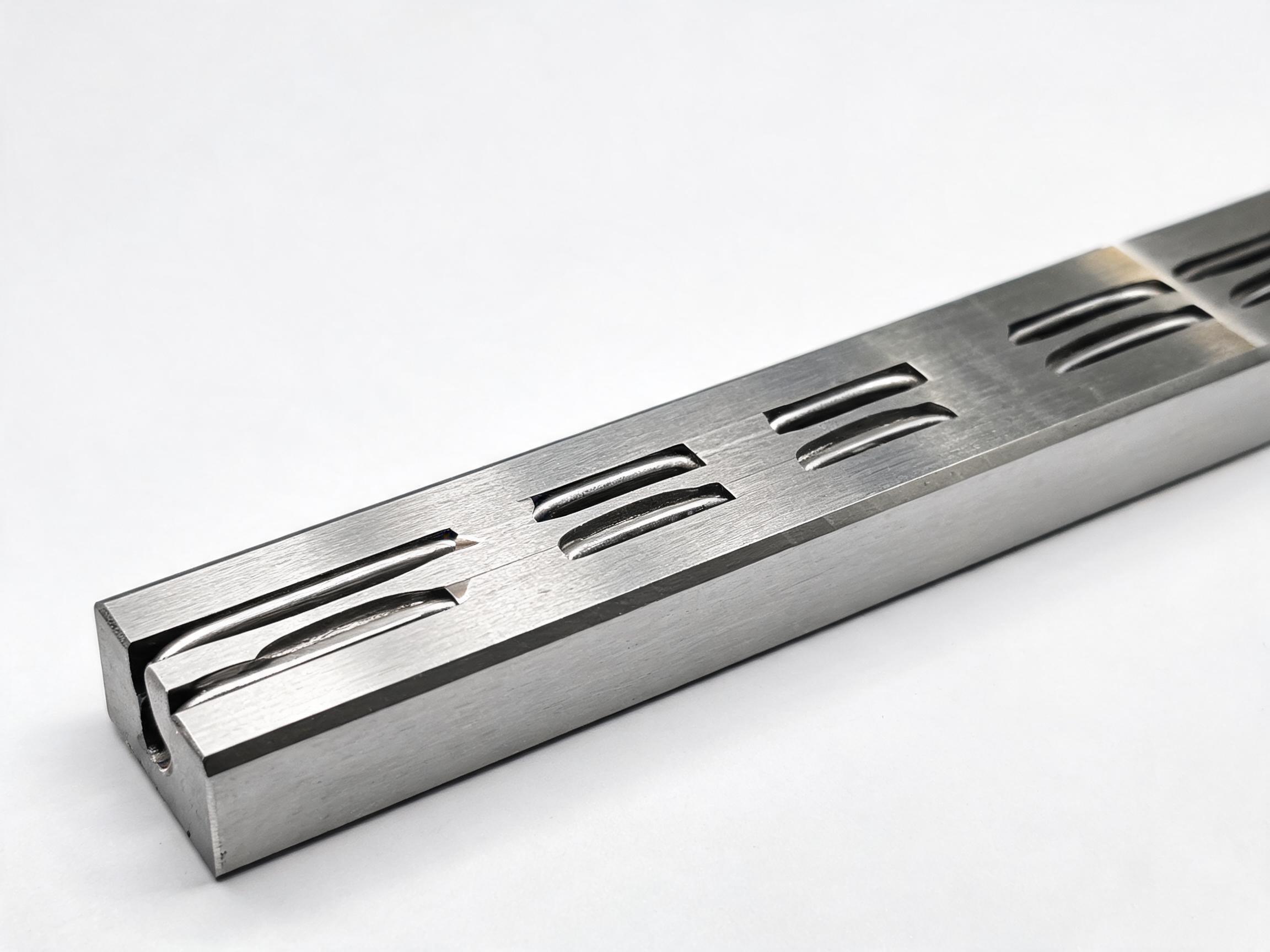
A step-by-step configuration guide for machine builders specifying profile rail linear guides. Using HGR series data, this article walks through five decisions—rail size, carriage fit, accuracy grade, mounting, and length/splicing—and explains what each choice changes in practice.
Buyer configuration guide
You have already decided that a profile rail linear guide system is the right motion component for your machine. The next job is configuration: translating load, stroke, mounting envelope, and accuracy requirements into a specific rail size, carriage, grade, bolt pattern, and rail length. This guide walks through five decisions in the order they affect each other, using HGR series data as the working example. Each decision changes what the next one can be, so the sequence matters.
HGR series profile rail linear guides are available in rail sizes 15, 20, 25, 30, 35, and 45. Running surfaces are induction hardened to 58–62 HRC. The base rail steel is a high-carbon steel; the exact grade varies by size, so confirm the grade for your selected size on the datasheet rather than assuming one grade across the range.
Decision 1: Rail size
Rail size is the first decision because it fixes the cross-section, the mounting hole pitch, and the load range available to you. In the HGR series, size 45 has a 45 × 38 mm cross-section, a hardened layer of 2.0–2.5 mm, and a rail weight of 6.2 kg/m. Its mounting hole pitch is 60 mm with M12 bolts. Smaller sizes in the range step down in cross-section and bolt size accordingly.
What this decision changes: the dynamic and static load ratings you can reach. For reference, the HGR20 rail with its matched carriage is rated 16.7 kN dynamic and 26.7 kN static. The HGR45, paired with an HGW45CA carriage, is rated 62.8 kN dynamic and 112 kN static. That is a large step, and it is the main reason to start with load and moment rather than with a preferred size.
To choose, calculate the load per carriage under your actual acceleration and overhung-load conditions, then compare against the rating for the candidate size. If your calculated load sits close to the rating of a smaller size, the next size up is usually the practical choice because the rating is a catalog value under defined conditions, not a service guarantee for your machine.
See the full HGR series heavy-duty linear guideway rail range for the size list and matched carriages.
Decision 2: Carriage fit
Carriage fit is not a free choice. Each rail size accepts a defined carriage family, and the carriage determines the mounting interface on the moving side. In the HGR45 example, the HGW45CA carriage is the matched unit and carries the 62.8 kN dynamic / 112 kN static rating quoted above. The HGR20 figure is likewise a rail-plus-carriage pair rating.
What this decision changes: the height and width of the moving block, the bolt pattern on the carriage top, and the load rating. If your machine design already fixes the carriage mounting height because of a ball screw or belt drive, that height constrains which carriage you can use, and therefore which rail size is compatible. Work the fit from both ends: the load requirement pushes the size up, and the drive-train height pushes it back down. The configuration that satisfies both is the one to specify.
For very large sizes and heavy-duty applications, the HGR45 heavy-duty large linear guideway rail page gives the size-45 cross-section, hardened layer, and carriage pairing in one place.
Decision 3: Accuracy grade
The HGR series offers two accuracy options: ground H (P5) and rolled N (P7). The grade affects parallelism, running smoothness, and the manufacturing route, and it is one of the few decisions where the application rather than the load governs.
What this decision changes: the tolerance band over the rail length and the consistency of carriage travel. Ground H (P5) is the tighter option and is specified where the machine's positioning or surface finish depends on rail straightness. Rolled N (P7) is the standard-precision option and suits applications where the rail provides guidance and the positioning is handled elsewhere in the system.
A common mistake is to specify the tighter grade by default. The grade should be selected from the error budget of the machine: if the rail's contribution to positioning error is small relative to the drive and feedback, the tighter grade adds cost without changing the result. Conversely, if the rail is a dominant error source, downgrading to save cost will show up in the finished part.
Note also that the base steel grade varies by size. Because the accuracy grade and the steel grade are separate specifications, confirm both on the datasheet for the size you select rather than carrying a value from one size to another.
Decision 4: Mounting details
Mounting is where the earlier decisions become a drawing. For HGR45, the rail mounts on a 60 mm hole pitch with M12 bolts. The bolt size and pitch follow from the rail size: larger rail sections use larger bolts and wider spacing. The carriage side has its own bolt pattern, set by the carriage model chosen in Decision 2.
What this decision changes: the hole pattern in your base casting or machined plate, the counterbore or through-hole detail, and the assembly sequence. Because the rail is induction hardened to 58–62 HRC on the running surfaces, the mounting holes are the features you must locate accurately; the hardened surface itself is not a machining datum after hardening.
Two practical points belong in the drawing. First, specify the rail reference edge and the carriage reference edge, since a profile rail system is located against a shoulder on both sides. Second, confirm the bolt grade and preload torque with the supplier for the selected size rather than reusing values from a smaller rail.
If you are comparing a profile rail system against a round-shaft arrangement, note that the mounting logic is different: a round-shaft linear guide rail unit with bearing block is supported along its length by shaft supports, whereas a profile rail carries its load through the rail cross-section and mounts to a flat, machined surface. The hole pattern and surface preparation requirements therefore differ.
Decision 5: Length and splicing
Length is the last decision because it depends on the stroke, the carriage length, and the end margins you have already fixed. For HGR45, the standard maximum length is 4000 mm, with splicing to approximately 8000 mm. The rail weight of 6.2 kg/m is the figure to use when checking handling and shipping.
What this decision changes: whether you need a single-piece rail or a spliced rail, and how the joint is handled. A spliced rail requires the joint to be positioned and aligned so that the carriage transitions without a step. The joint location relative to the stroke and the carriage travel must be specified, not left to the supplier.
Beyond the standard maximum, splicing extends the usable length to roughly 8000 mm. If your stroke requires a longer rail than that, the configuration changes: multiple rails in line, or a different motion concept. The minimum order quantity for HGR45 is 30, which matters when you are prototyping and when you plan spare rails. Because rail length and splicing are fixed at order, they should be finalized before the purchase order rather than after.
Configuration summary
| Decision | What it sets | HGR data point |
|---|---|---|
| Rail size | Cross-section, bolt pattern, load range | Sizes 15–45; HGR45: 45 × 38 mm, 60 mm pitch, M12 |
| Carriage fit | Moving-block height, top bolt pattern, rating | HGR20 + carriage: 16.7 kN dyn / 26.7 kN stat; HGR45 + HGW45CA: 62.8 kN dyn / 112 kN stat |
| Accuracy grade | Tolerance band and travel consistency | Ground H (P5) or rolled N (P7) |
| Mounting | Hole pattern and assembly sequence | HGR45: 60 mm pitch, M12 bolts |
| Length and splicing | Single piece or spliced, joint location | HGR45: standard max 4000 mm, splicing to ~8000 mm, 6.2 kg/m, MOQ 30 |
What to put on the inquiry
Once the five decisions are made, the inquiry can be specific: rail size, carriage model, accuracy grade, rail length, whether splicing is required, and the mounting hole pattern. Include the calculated load per carriage and the stroke. With those inputs, the supplier can quote a matched rail-and-carriage set rather than a rail alone. The HGR series carries an 18-month warranty; confirm the warranty terms and the datasheet values for your selected size when you request the quotation.