
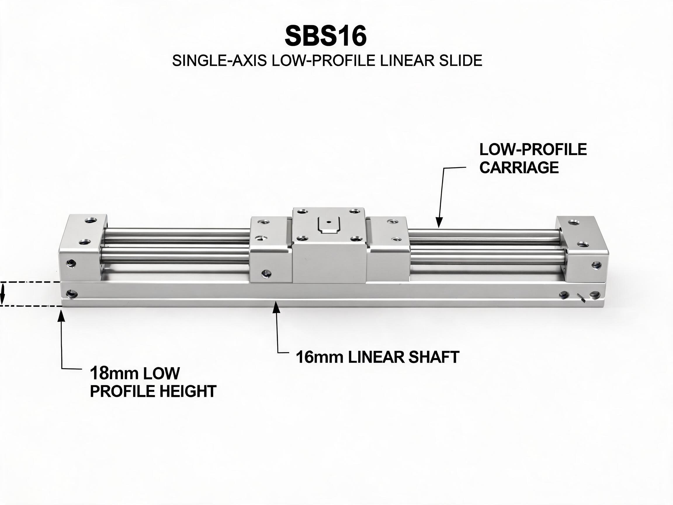
The SBS16 slide unit is a 16 mm shaft single-axis slide with an 18 mm total height. This selection explainer covers where that low profile actually helps, what it costs you in moment capacity, and how to decide between the SBS16 and a taller SBR16 rail unit.
Slide Unit Selection
The SBS16 has one number that defines it: 18 mm total height. Everything else about this 16 mm shaft slide unit follows from that figure. If your mounting envelope is fixed and the carriage must sit low, the SBS16 is the unit you check first. If you have height to spare and the load carries an overhung moment, a taller rail unit usually serves you better. This article explains which condition you are in.
Key takeaways
- SBS16 is built on a 16 mm shaft with an 18 mm total height — the defining dimension for tight envelopes.
- Rated 5.2 kN dynamic and 8.0 kN static, with 25 mm mounting hole pitch and standard lengths of 150–500 mm (1000 mm custom).
- The lower carriage height reduces moment capacity compared with taller bearing-block units; this is a load trade-off, not a defect.
- SBR16 is the taller alternative: 7.8 kN dynamic / 12.0 kN static, 50 mm hole pitch, lengths up to 2000 mm (4000 mm custom).
In this article
What the SBS16 slide unit is
The SBS16 is a single-axis linear motion slide unit made by Dongfeng Bearing. It runs a low-profile carriage on a 16 mm shaft, and the assembled unit measures 18 mm in total height. The low-profile carriage is the reason the number stays that low; a conventional bearing-block carriage on the same shaft diameter sits considerably taller.
Published load ratings for the SBS16 are 5.2 kN dynamic and 8.0 kN static. Those figures describe the unit's rated capacity as listed in the catalog. They are not a statement about any particular machine's duty cycle — your working load, speed, acceleration and moment arm all sit on top of the rating.
The unit is listed as a complete slide assembly: shaft, carriage and mounting provisions. In machine-building terms that means you mount the shaft to your structure, attach the moving member to the carriage, and the axis is done — there is no separate profile rail to design in, as there is with a profile-guideway system. The current listing does not describe a separate support rail for the shaft; how the shaft should be supported over longer lengths is a drawing-level question to confirm per datasheet.
Where 18 mm total height matters
Total height is one of the first dimensions a machine builder runs out of. Three situations make the SBS16 worth a look.
A tight vertical envelope
When the space between a fixed frame and a moving plate is fixed by something you cannot change — a machine base, a conveyor frame, a guard — the slide has to fit inside it with clearance for the carriage and its mounting screws. An 18 mm overall height leaves room where a taller bearing-block unit would force you to raise the whole assembly or cut the frame.
Retrofitting under an existing frame
Retrofit work is unforgiving: the surrounding structure stays, and only the motion axis changes. If the old axis was thin and the new one has to occupy roughly the same slot, a low-profile slide is the practical choice. The 18 mm height is also useful when the carriage has to pass under a cross member or over a low base plate during travel.
Low-profile gantries and pick-and-place heads
On a gantry, every millimetre of carriage height adds to the stack above the rail — and that stack height translates directly into a longer moment arm on the bearings. A low carriage keeps mass close to the rail line, which suits heads where the payload hangs close to the axis. It also keeps the overall machine height down, which matters on bench-top and enclosed equipment.
One caveat applies to all three: if the frame is already tall and the envelope is generous, the low profile buys you little. Height savings only count when height is the constraint.
The load trade-off of a low profile
A low carriage has a shorter vertical distance between the load line and the bearing support. That shorter lever cuts both ways: it reduces the moment arm for loads hanging near the rail, but it also reduces the bearing unit's own ability to resist a given moment compared with a taller block. When a load is offset from the carriage centre — a gripper at the end of a bracket, an overhung tool, a payload that swings during acceleration — that reduced moment capacity shows up as lower permissible offset or lower speed.
So the honest reading of the SBS16 ratings is this: 5.2 kN dynamic and 8.0 kN static apply to the rated configuration. How much of that capacity you can actually use depends on where the load sits relative to the carriage. A tall bearing block gives you more margin for overhung loads for the same shaft size; a low-profile carriage gives you less, and exchanges that margin for envelope.
Precise moment ratings for the SBS16 carriage are not in the current records — confirm per datasheet for the specific carriage variant and load direction before you size an overhung application.
Travel and mounting
The SBS16 mounting hole pitch is 25 mm. Standard lengths run from 150 mm to 500 mm, with 1000 mm available as a custom length. Minimum order quantity is 50 units.
The 25 mm pitch is a useful design constraint to know early. It is half the 50 mm pitch of the SBR16, which means you get more mounting points per metre of shaft and can place the fixing screws closer to the load — convenient on short-stroke axes and on frames where you cannot drill a sparse pattern. On a 150 mm length you have a short axis with a few fixing points; on a 1000 mm custom length the same pitch keeps the shaft well supported along its run, though deflection of a long, unsupported shaft section is a separate question that depends on your mounting structure, not just the slide.
For travel beyond the standard range, the practical limit is usually the shaft's own stiffness and your structure, not the carriage. If you need long travel with the same height budget, state the length and load together and let the supplier review the shaft support arrangement.
SBS16 versus SBR16, side by side
The SBR16 is the natural alternative: the same 16 mm shaft nominal size, but built as a rail unit with a bearing block and an aluminium support rail. The two are not interchangeable in every machine; they solve different problems.
| Specification | SBS16 | SBR16 |
|---|---|---|
| Shaft diameter | 16 mm | 16 mm (GCr15 shaft, HRC 58–62) |
| Carriage type | Low-profile carriage | Double-row ball bearing block |
| Total height | 18 mm | Taller unit; exact height confirm per datasheet |
| Dynamic load rating | 5.2 kN | 7.8 kN |
| Static load rating | 8.0 kN | 12.0 kN |
| Support rail | None listed — shaft-and-carriage assembly; support arrangement confirm per datasheet | 6063-T5 aluminium support rail |
| Mounting hole pitch | 25 mm | 50 mm |
| Standard lengths | 150–500 mm (1000 mm custom) | Up to 2000 mm (4000 mm custom) |
| MOQ | 50 | 50 |
What the table actually tells you
The SBR16 carries about 50 percent more dynamic load (7.8 kN versus 5.2 kN) and the same 50 percent step in static load (12.0 kN versus 8.0 kN) compared with the SBS16. That is the price of the low profile, and it is a meaningful difference if your axis handles a heavy overhung load. The SBR16 also brings a hardened GCr15 shaft at HRC 58–62 on a 6063-T5 aluminium support rail — a full-length support that resists shaft deflection, which is why it is listed up to 2000 mm standard and 4000 mm custom. The SBS16 is listed to 500 mm standard and 1000 mm custom, and its shaft support arrangement over longer lengths should be confirmed per datasheet.
The hole pitch difference follows from the design: 25 mm gives the low-profile unit denser fixing points, 50 mm gives the rail unit a sparser, heavier pattern suited to longer spans. Neither is better in the abstract; they match different lengths.
How to choose between them
Work through these in order. The first condition that applies usually settles it.
- Is total height a hard constraint? If the envelope is fixed and a taller unit forces you to modify the surrounding frame, SBS16. If you have room, continue.
- Is the load overhung or moment-heavy? A gripper at the end of a bracket, a tool offset from the carriage centre, or high acceleration with an elevated payload argues for the SBR16's extra moment capacity. If the payload sits close to the rail line and the datasheet moment rating covers your arm, the SBS16 is the candidate to check first — get the moment rating confirmed before you commit.
- How long is the travel? Beyond roughly 500 mm, the SBR16's supported rail and 2000 mm standard range are the obvious route. Inside 500 mm, either model works on length alone.
- What does your drawing already fix? If the hole pattern is set at 25 mm, the SBS16 is the closer match; at 50 mm, the SBR16. Changing a fixed mounting pattern ripples into the frame design.
If two conditions conflict — say, a tight envelope and a long overhung load — the decision needs the actual load figures and the datasheet moment ratings for each carriage, which is worth requesting before you commit. Dongfeng Bearing lists both models from an MOQ of 50; the product pages give the full listed specifications.
Questions buyers ask
Can the SBS16 replace an SBR16 directly?
Not as a drop-in in most cases. The mounting hole pitch differs (25 mm versus 50 mm), the total height differs, and the SBR16's load ratings are higher. A direct swap usually requires redrilling or a new mounting plate, and you should recheck the load case against the SBS16's lower ratings.
What is the maximum length of an SBS16?
Standard lengths are 150–500 mm, with 1000 mm available as a custom length. For anything beyond that, the SBR16's supported rail extends to 2000 mm standard and 4000 mm custom.
Is the SBS16 rating enough for a light pick-and-place axis?
At 5.2 kN dynamic and 8.0 kN static, the rated capacity is well above what most light heads demand in pure load terms. The limiting factor is more often the moment arm from an offset payload and the acceleration profile, so check the carriage moment rating per datasheet once you have the head's actual geometry — until that figure is confirmed, treat the load case as unverified.