
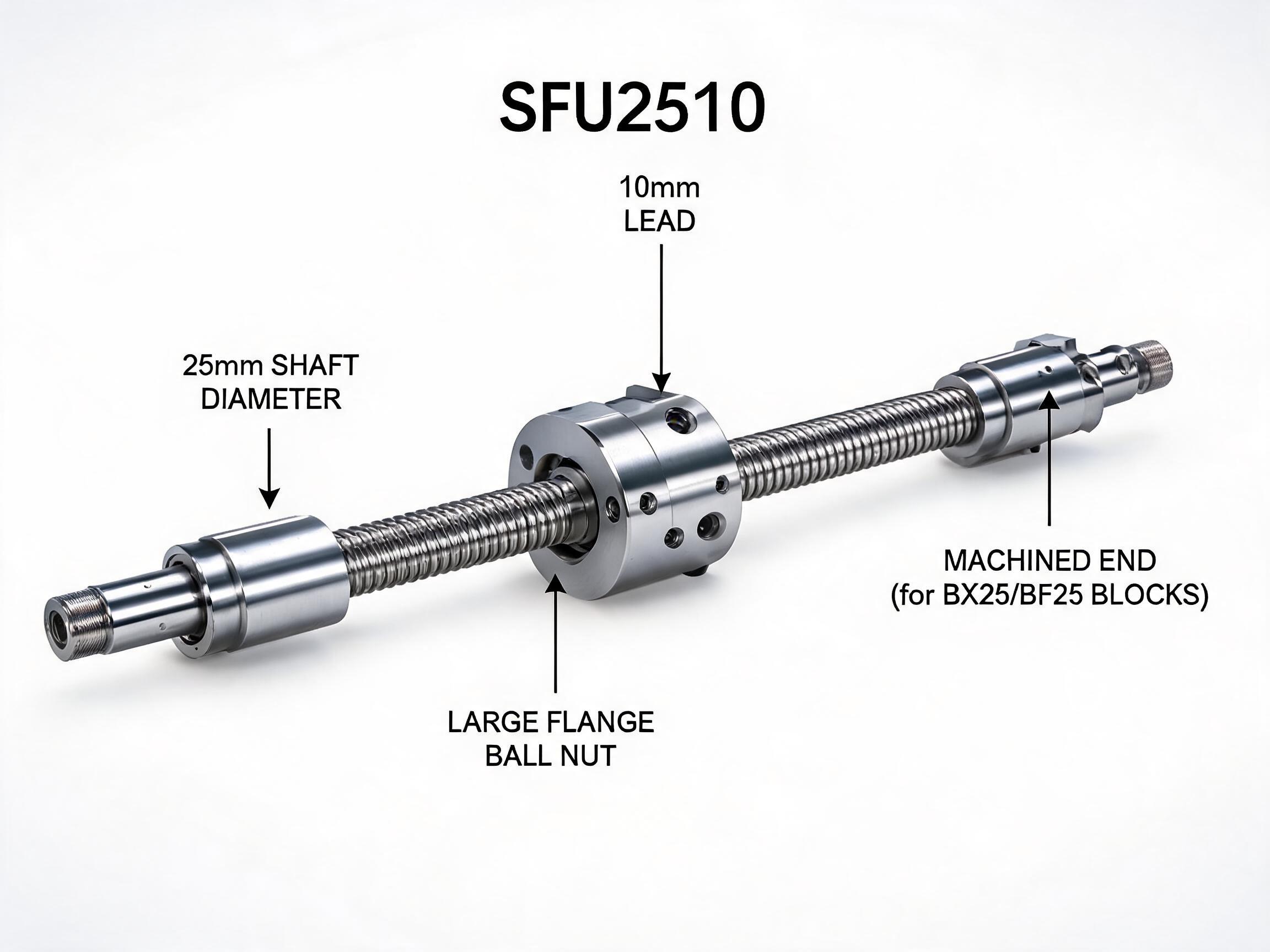
A field-by-field reading of the SFU2510 rolled ball screw: how the 25 mm shaft diameter and 10 mm lead are encoded in the model number, the exact listed specifications (C7 accuracy, ±0.05 mm/300 mm travel error, 17.2 kN dynamic load), and a plain guide to when this size fits a machine and when a smaller or larger screw is the better choice.
Model number, decoded
Two numbers in the model code answer the first two questions most buyers ask about a rolled ball screw: how thick the shaft is and how far the nut travels per turn. SFU2510 carries both, and the rest of the code fixes the series, accuracy class and nut style that come with them.
- SFU marks the rolled-screw series; the number 25 is the nominal shaft diameter in millimetres.
- The 10 is the lead: linear travel per full revolution of the screw.
- Every specification below applies to a 25 mm / 10 mm C7 rolled assembly, not to the SFU family as a whole.
Reading SFU2510 one character group at a time
The model code is not a random label; it is a compressed spec sheet. Split it into SFU / 25 / 10 and you have the three facts that decide most of the mechanical fit.
SFU: the rolled series
The SFU prefix identifies a cold-rolled ball screw, where the groove is formed by rolling rather than by grinding. That single difference from ground screws shapes the rest of the datasheet: rolled screws are positioned as a cost-effective option where C7 accuracy is acceptable, and this SFU2510 is listed at exactly that class.
25: shaft diameter
The 25 means 25 mm nominal shaft diameter. At this size the screw is no longer a small positioning element; it is a structural shaft that must carry axial load, resist buckling and be supported at both ends. That is why the shaft-end machining on this model is listed as compatible with BK25/BF25 support units.
10: lead
The 10 is the lead in millimetres, the distance the nut advances per full turn. Ten millimetres per revolution sits in the middle range of common leads: fast enough for rapid moves without demanding high motor speed, but coarse enough that a small rotary input produces a large linear output. The trade-off is resolution. Ten millimetres divided by the steps of your drive train gives the travel per step or per encoder count, so a 10 mm lead assumes the positioning accuracy you need is coarser than what a 1 or 2 mm lead screw would deliver.
SFU2510 listed specifications
The table below is the configuration as listed for this model. These values describe a 25 mm diameter, 10 mm lead, C7 rolled screw with a single-flange preloaded nut; they are not a statement about other SFU sizes.
| Item | Listed value |
|---|---|
| Model | SFU2510 |
| Screw type | Cold-rolled ball screw |
| Nominal shaft diameter | 25 mm |
| Lead | 10 mm |
| Accuracy class | C7, marked to ISO 3408 |
| Travel error | ±0.05 mm / 300 mm |
| Dynamic load rating | 17.2 kN |
| Static load rating | 26.5 kN |
| Material | GCr15 bearing steel |
| Raceway hardness | HRC 58–62 |
| Standard length range | 300–3000 mm |
| Nut | Single flange, preloaded |
| Shaft-end compatibility | BK25 / BF25 support units |
| Minimum order quantity | 50 pieces |
Values as listed for the SFU2510 assembly. Length and shaft-end details are configured per order within the stated range. Some annotated product artwork labels the machined ends for BX25/BF25 blocks; the compatibility listed for this model is BK25/BF25, so treat the machined-end drawing and this listed code as the ordering reference and confirm the end configuration with the datasheet.
What the numbers mean in use
The travel error figure is the one most often misread. ±0.05 mm over 300 mm is a cumulative error allowance for the assembled screw, not a specification of how accurately any single point on the shaft is positioned. Over a longer travel the error accumulates according to the same standard, which is why C7 suits general positioning and transport axes rather than precision metrology stages.
The two load ratings answer different questions. The 17.2 kN dynamic rating applies when the screw is moving under load and is the figure to use for fatigue life and for sizing the shaft against the repeated axial force of your application. The 26.5 kN static rating applies to a screw at rest or moving slowly under a load that may be applied once, such as during a hold or a crash condition.
For buyers comparing sizes: the listed dynamic rating of this 25 mm screw is roughly 2.5 times that of an SFU1605. If a design team is stepping up from a 16 mm screw because the original unit was load-limited, that ratio is the reason a 25 mm shaft appears in the revised drawing.
The GCr15 bearing steel and HRC 58–62 raceway hardness describe the material state of the screw and nut, and the standard length range of 300 to 3000 mm tells you what can be supplied without a custom length request. Shaft-end machining that suits BK25/BF25 support units means the end journals, thread and keyway are already defined around those bearing blocks, so the support choice is made for you once you order this model.
When SFU2510 is the right fit
This model suits applications where the axes need a medium-to-heavy axial push, moderate positioning accuracy and travel speeds that a 10 mm lead can serve. Typical conditions look like this:
- The required axial thrust approaches the range the 17.2 kN dynamic rating supports, and a smaller shaft would be marginal on buckling or fatigue.
- Positioning tolerance is in the ±0.05 mm per 300 mm band, or the axis is not the accuracy-limiting element of the machine.
- Stroke is long enough to benefit from a coarse lead: a 10 mm lead keeps screw rpm down for a given traverse speed, which matters when the screw is long or the drive is speed-limited.
- Both ends can be fitted with BK25/BF25 support blocks, and the design already works around 25 mm bore bearings and housings.
- Order quantities are in the range of 50 pieces or more, since that is the stated minimum for this model.
When another size is the better call
The same code structure helps you rule this model out quickly.
- If the application needs fine incremental resolution, a 10 mm lead is coarse. A smaller lead on the same diameter gives more linear precision per motor turn; check the finer-lead variants of the SFU series before committing.
- If the axial load is well below what a 16 mm shaft handles, this screw is oversized. Larger diameter means more inertia, more cost and larger bearing blocks.
- If positioning accuracy must be tighter than the C7 travel-error band, a ground screw in a higher class is the appropriate family rather than a rolled SFU.
- If the machine envelope cannot accept BK25/BF25 housings, the shaft ends will need to be re-machined for a different support, which is a custom configuration rather than this standard model.
- If order volume is below 50 pieces, the standard configuration on this model does not meet the stated MOQ as-is.
Checking a drawing against the model code
Before sending an RFQ for SFU2510, the useful check is not whether the model number is right; it is whether the surrounding drawing matches what 25 mm and 10 mm imply. Confirm the following on your side:
- The nut mounting flange on the machine matches a single-flange nut with preload.
- The stroke plus nut length plus end machining falls inside the 300–3000 mm standard length range, or the drawing must state the exact overall length required.
- The drive sizing assumes 10 mm of travel per revolution, including the resulting motor speed at the maximum traverse rate.
- Support blocks are dimensioned for 25 mm shaft ends with the BK25/BF25 pattern.
- Quantity is declared at or above 50 pieces, or the request identifies it as a trial order for the supplier to quote separately.
Those five points cover the parameters that change from one machine design to the next. Anything still open in them is where the supply conversation should start.
Next step: see the full configuration, length options and drawing details on the SFU2510 rolled ball screw assembly with flange nut page. If you are still comparing diameters or leads, the SFU series rolled ball screw range lists the alternatives in the same format, so the model codes can be read side by side.