
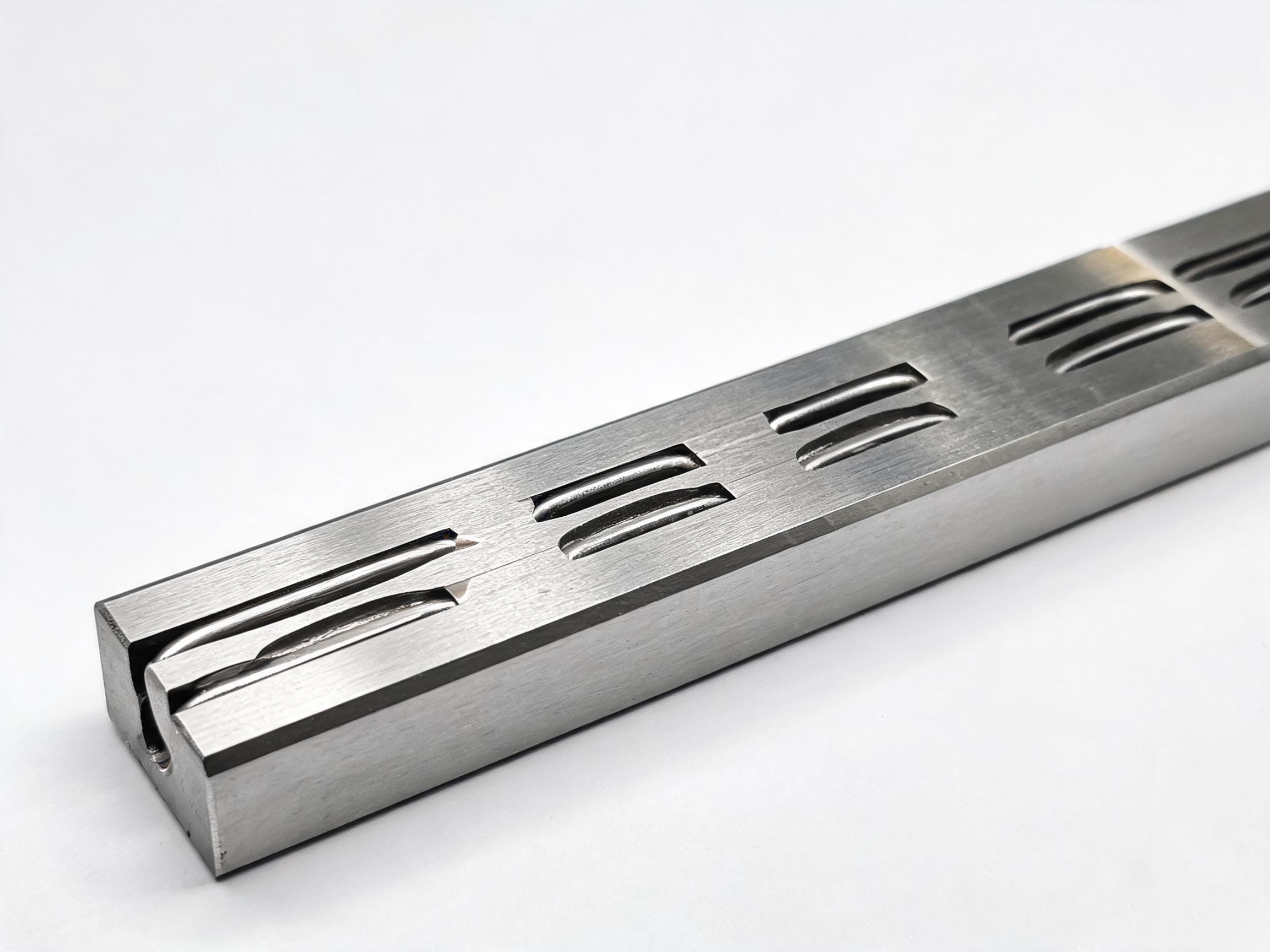
A practical sizing guide for machine builders choosing a linear guide rail: which machine motions run on a rail-and-carriage guideway, how rail size follows load per carriage and stroke, when to pick the Ground H (P5) or Rolled N (P7) accuracy version, and what a long axis means for rail length, joints and lubrication. Written from an engineer's view by Xiamen Dongfeng Bearing Mechanical & Electrical Co., Ltd., manufacturer of the HGR Series Heavy-Duty Linear Guideway Rail.
Sizing Guide for Machine Builders
Choosing a linear guide rail for a machine axis usually comes down to four decisions: does this motion belong on a rail-and-carriage guideway at all, what rail size carries the load, which accuracy version the axis can work with, and how long the rail can be before length itself changes the design. The notes below answer those four questions in the order a machine builder faces them.
Key takeaways
- Rail-and-carriage guideways suit guided, repeating linear motion under load — positioning axes, gantries, transfer and handling strokes.
- Rail size tracks the load carried by each carriage and the stiffness the axis needs, not the total machine weight.
- Ground H (P5) and Rolled N (P7) are accuracy classes, not quality grades; the choice follows the positioning and running smoothness the axis demands.
- HGR rail is available up to 4000 mm with customisation, so long axes are usually built from butted rail sections.
- Lubrication is a design decision: the HGR rail carries an oil groove and oil nipple, so plan the lube path before the axis is assembled.
On this page
Which machine motions need a rail guideway
A rail-and-carriage guideway is worth specifying when a load has to travel in a straight line repeatedly, stay aligned with another axis, and be positioned or moved under load. That covers a large share of machine motions:
- Positioning axes. Any axis that carries a tool, a sensor or a workpiece to a commanded position and back, cycle after cycle.
- Gantry and bridge axes. Motions where two rails support a span and the carriage has to run parallel to a second rail without binding.
- Transfer and handling strokes. Pick-and-place, loading and unloading, shuttle and pusher motions where the carriage repeats the same stroke thousands of times.
- Support axes under a moving head. The rail carries the moving mass and sets the straightness the process sees, even when the drive handles the motion.
The common thread is guided motion with a defined stroke and a load the carriage must carry. A short, low-load, one-off movement that is not repeated and not guided by the machine structure rarely justifies a rail guideway; a repeating guided stroke under load usually does, because the rail fixes both the line of travel and the alignment between the moving part and the machine frame.
How rail size follows load per carriage and stroke
Rail size is chosen from the load carried by each carriage, the moment that load creates, and how much deflection the process can tolerate. It is not chosen from the mass of the whole machine. Two identical machines can need different rail sizes if one has a heavier moving head or a longer stroke that shifts the load further from the carriage.
The HGR Series Heavy-Duty Linear Guideway Rail is made in six sizes: HGR15, HGR20, HGR25, HGR30, HGR35 and HGR45. Load capacity rises with size. As a reference point, the HGR20 rail carries a dynamic load of 16.7 kN and a static load of 26.7 kN. Those figures describe the rail itself; a sizing check still has to compare them against the actual load per carriage and the resulting moment, with a margin that matches the duty cycle.
| Rail size | Role in a sizing check |
|---|---|
| HGR15 | Smallest of the series — light carriages and short strokes. |
| HGR20 | 16.7 kN dynamic / 26.7 kN static — a common mid-range reference. |
| HGR25 / HGR30 | Larger sizes for heavier carriages or longer moment arms. |
| HGR35 / HGR45 | Largest sizes in the series for high-load, high-stiffness axes. |
Two rules keep the choice honest. First, size the rail for the carriage that carries the most load, not the average carriage — a gantry with two carriages can be dominated by one of them when the head sits off-centre. Second, check the moment, not just the vertical load: the same 16.7 kN rail behaves differently under a load applied 50 mm from the carriage centre and one applied 300 mm away, because the moment arm grows with the offset. A longer stroke increases that offset when the head reaches the end of travel, so stroke and rail size are checked together, not one after the other.
When the sizing result is close between two sizes, the decision usually turns on stiffness and deflection tolerance rather than on the load figure alone. A process that tolerates more deflection can stay on the smaller rail; a process that does not usually steps up one size.
Ground H (P5) versus Rolled N (P7)
The HGR rail is offered in two forms:
- Ground H version, accuracy class P5. The raceways are ground.
- Rolled N version, accuracy class P7. The raceways are rolled.
P5 and P7 are accuracy class names, and the class describes the running accuracy the rail is made to — not how well the rail is made. Both versions are produced from the same material basis: 55# high carbon steel, with raceways induction hardened to 58-62 HRC. The hardening applies to both, so the choice between them is a question of what the axis needs, not of which one is tougher.
The decision follows the axis duty:
- Ground H (P5) is the version for axes where positioning accuracy and smooth running at speed matter — a positioning or measuring axis, or a machine where the finished part reflects the straightness of the rail.
- Rolled N (P7) is the version for axes where the motion is a transfer or handling stroke, or where the process tolerance is wide enough that the accuracy class of the rail is not the limiting factor.
Because the classes are named rather than expressed as tolerances here, the practical approach is to state the positioning requirement of the axis and let the class be matched to it. If the axis requirement sits between the two classes, the ground version is the safer choice, on the basis that the rail is then not the tightest item in the tolerance chain. If the axis is a simple transfer stroke, the rolled version avoids paying for accuracy the process does not use.
Rail length and what a long axis implies
HGR rail is available in lengths up to 4000 mm with customisation. That maximum shapes how long axes are built. A single-piece rail covers strokes up to the limit; beyond it, the axis is assembled from more than one rail section butted end to end on the same mounting surface.
A long axis therefore implies three things to check during design:
- How many sections and where the joints fall. Joints are placed so the carriage is not sitting across a joint at a critical position, and so the joint does not land where the mounting surface is least stiff.
- Mounting-surface straightness along the full length. The rail follows the surface it is bolted to. A long axis needs the mounting surface prepared along its whole length, not only under the first section.
- Parallel alignment between two rails. On a gantry or bridge, the two rails have to be aligned to each other over the full stroke. On a long axis this is the step that most often determines whether the carriage runs freely or binds.
Rail length is also where the stroke margin lives. The rail has to be long enough to give the carriage the full stroke plus the carriage length plus the end margins the machine needs, so the ordered rail length is normally longer than the stroke figure on the drawing. Confirm the ordered length against the drawing before release, because a rail cut short cannot be extended later.
Lubrication as an installation planning point
Lubrication is easier to plan before the axis is assembled than to add afterwards. The HGR rail has an oil groove and an oil nipple for lubrication, so the lube path can be designed into the axis rather than routed around it.
Two points belong in the installation plan. First, decide how the lubrication reaches each carriage — a single feed point or a distributed line — and check that the chosen route clears the carriage through the full stroke. Second, treat the oil nipple location as a fixed point on the rail drawing, so the lube line is not trapped behind a carriage or inside a frame after assembly. On a multi-section rail, the same question is repeated at each section, which is one reason lubrication is settled alongside rail length rather than after it.
FAQ
What is an LM guideway?
“LM” stands for linear motion. An LM guideway is the rail-and-carriage assembly that guides a load along a straight line: a profiled rail with hardened raceways, and one or more carriages that run on balls between the rail and the carriage. In everyday procurement language, “LM guideway” and “linear guide rail” usually refer to the same component. For a fuller explanation of what the assembly is and how it differs from a linear bearing, see the guideway overview on our topics pages.
What are linear guide rails used for?
They are used wherever a load has to move in a straight line repeatedly and stay aligned while doing it: positioning axes, gantry and bridge axes, transfer and handling strokes, and support axes under a moving head. The rail sets the line of travel and the alignment; the drive provides the motion. The section above, Which machine motions need a rail guideway, lists the cases where a rail guideway is worth specifying.
How do I choose a linear guide or select a guideway?
Work through four items in order: the load carried by each carriage and the moment it creates, the accuracy class the axis needs (for HGR, Ground H in P5 or Rolled N in P7), the rail length against the required stroke, and the lubrication route. Then match the result to a rail size — HGR15, HGR20, HGR25, HGR30, HGR35 or HGR45 — and confirm the load figures for that size. If you can share the load per carriage, the stroke and the positioning requirement, we can check the sizing against the HGR Series data with you.
Sizing the HGR Series for your axis
The HGR Series Heavy-Duty Linear Guideway Rail is made in HGR15, HGR20, HGR25, HGR30, HGR35 and HGR45, in a Ground H version to accuracy class P5 and a Rolled N version to accuracy class P7, with raceways induction hardened to 58-62 HRC in 55# high carbon steel and lengths up to 4000 mm with customisation. Minimum order quantity is 50 pieces. Full specifications are on the HGR Series Heavy-Duty Linear Guideway Rail page. If you send the load per carriage, the stroke and the accuracy requirement of the axis, we can help match the rail size and version to the duty.