
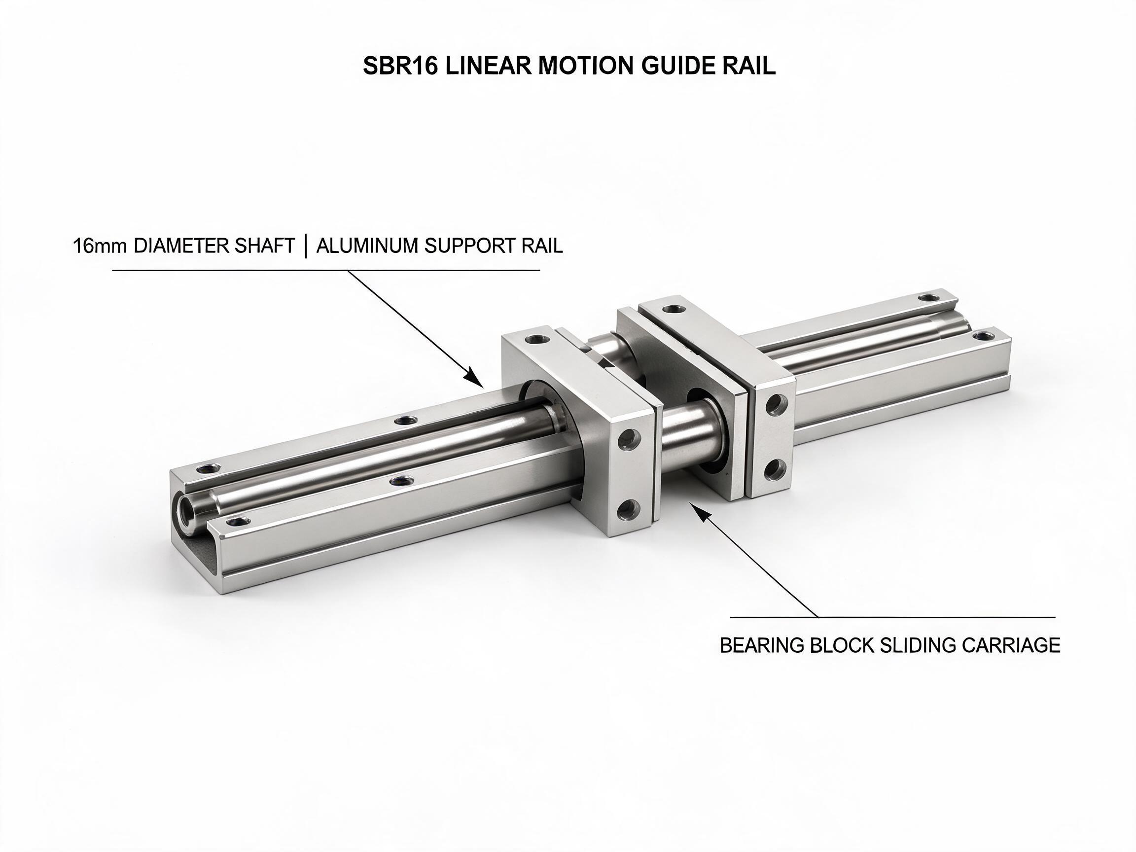
A practical selection guide for buyers comparing SBR and TBR round-shaft linear guide units against profile rails. It explains how the aluminum support rail changes deflection, where integrated shaft units remain the right choice by load, span, environment and budget, and when the crossover to profile rails becomes necessary.
Linear Motion Selection Guide
Round-shaft linear guides are often dismissed too early. In many machines they do the job at lower cost and with simpler mounting than profile rails. In others they are the wrong choice, and the failure shows up as deflection, wear or vibration long after the machine is installed.
This guide looks at integrated round-shaft units — shaft, aluminum support rail and bearing block supplied as one system — and where the crossover to profile rails becomes necessary. It covers the SBR and TBR families, why the support rail matters more than the shaft diameter alone, and a checklist you can take into the next machine design review.
Key takeaways
- An integrated support rail changes deflection behavior compared with a bare shaft on pillow blocks, because it limits shaft bending along the supported length.
- SBR and TBR units are usually enough for moderate loads, short-to-medium strokes and general automation frames.
- High moment loads, long unsupported spans, high duty cycles and tight running parallelism push the design toward profile rails.
- Load per block, span, environment and budget are the four decisions that settle most cases.
On this page
- What an integrated unit actually includes
- Why the aluminum support rail changes deflection
- SBR and TBR: what each family suits
- The crossover checklist
- Specification reference
- Ordering and MOQ notes
What an integrated round-shaft unit actually includes
A bare round shaft on two pillow blocks is not the same product as an SBR or TBR unit, even when the shaft diameter matches. The integrated unit adds a continuous aluminum support extrusion running under the shaft, pre-drilled at a fixed pitch so the shaft is fastened down along its whole length rather than only at the ends.
The SBR16 unit is a clear example of the format: a GCr15 shaft hardened to HRC 58–62, a 6063-T5 aluminum support rail with mounting holes every 50 mm, and a double-row bearing block. It is rated at 7.8 kN dynamic and 12.0 kN static, with a maximum standard length of 2000 mm and custom lengths available to 4000 mm. Those are the numbers that matter when you start comparing it with a profile rail of similar envelope.
That configuration is what buyers mean when they search for an sbr linear guide: not a shaft, not a block, but the assembled axis.
Why the aluminum support rail changes deflection
Deflection in a round-shaft axis comes mostly from bending of the shaft between its supports. On a bare shaft with end-mounted pillow blocks, the free span is the full distance between those blocks, so a given load produces bending over that whole length.
Fitting the shaft into a continuous aluminum support rail changes the effective span. The rail carries the shaft along its length and the mounting holes tie it down at a fixed pitch, so the shaft is no longer free to bow as a single long beam. The result is a stiffer axis at the same shaft diameter, and the difference grows with length — which is why a supported unit can often replace a larger bare shaft in the same machine envelope.
The support rail does not make the axis infinitely rigid. It remains a round-shaft system with the deflection characteristics of that format, and the aluminum extrusion contributes its own behavior. The practical point for selection is that a supported unit and a bare shaft of identical diameter should not be treated as interchangeable in a deflection calculation.
SBR and TBR: what each family suits
SBR units are the general-purpose format: one shaft, one support rail, one or more bearing blocks running along it. They suit single-axis motion where the load is carried mainly in one direction and moment loads are modest.
The SBR20 dual-block unit uses a 20 mm shaft and is rated at 11.2 kN dynamic per block, so a dual-block arrangement on one axis gives 22.4 kN dynamic per axis. Maximum standard length is 3000 mm. That is enough for many transfer, positioning and handling axes that would otherwise be pushed toward profile rails on load grounds alone.
TBR systems take a different approach. In the TBR16 synchronized system, a single carriage spans two 16 mm shafts, with a center distance of 60, 80 or 100 mm. The carriage is rated at 15.6 kN dynamic and 24.0 kN static, and shaft parallelism is verified to plus or minus 0.02 mm over 1000 mm.
That last figure is the reason TBR exists as a separate family. When a carriage spans two shafts, any difference in friction or alignment between them produces yaw — the carriage tries to rotate in the horizontal plane rather than travel straight. A synchronized dual-shaft carriage constrains that rotation mechanically, so the axis resists yaw without relying on the drive or the frame to hold it straight.
| Format | Configuration | Dynamic rating | Static rating | Max standard length |
|---|---|---|---|---|
| SBR16 | 16 mm shaft, single support rail, double-row block | 7.8 kN | 12.0 kN | 2000 mm (custom 4000 mm) |
| SBR20 dual-block | 20 mm shaft, single support rail, two blocks | 11.2 kN per block (22.4 kN per axis) | — | 3000 mm |
| TBR16 synchronized | Carriage spanning two 16 mm shafts | 15.6 kN per carriage | 24.0 kN | — |
The crossover checklist
Four questions separate the cases where a round-shaft unit is the right answer from the cases where it is not. Work through them before the machine layout is fixed — changing the axis type later usually means changing the frame.
Load and moment
If the load acts roughly through the block and moment loads are small, a round-shaft unit is normally sufficient. Compare the actual load against the per-block rating and the number of blocks carrying it. When the application puts significant moment load on the carriage — an overhung tool, a long cantilever bracket, a load offset from the rail centerline — the moment capacity of the format, not just its radial rating, becomes the deciding figure.
If the moment load cannot be resolved by spacing blocks further apart or by using a TBR carriage, the axis has crossed over to a profile rail.
Span and support
The maximum standard length of the unit sets a practical limit on stroke. SBR16 is supplied to 2000 mm as standard, SBR20 to 3000 mm, with custom lengths available on request. Longer axes need either joined rails or a different format.
Span also interacts with deflection. Because the support rail ties the shaft down along its length, a supported unit tolerates a longer span than a bare shaft of the same diameter. But the frame underneath must still be stiff enough to hold the rails in alignment over that length — the support rail does not correct a frame that flexes.
Environment and duty
Round-shaft units in open machine frames are exposed. Dust, chips, coolant and washdown affect how long the bearing runs before service. Round-shaft blocks are commonly fitted with seals for these environments; confirm the seal specification and material with the supplier for the specific medium in your machine.
Duty cycle matters as much as load. A lightly loaded axis running continuously can wear faster than a heavier axis running intermittently. For high-duty applications, ask the supplier for the life and lubrication guidance that applies to the selected unit — the catalog rating alone does not answer this.
Running accuracy and parallelism
This is where round-shaft and profile-rail systems differ most clearly. A single SBR axis controls motion in one plane; parallelism between two axes depends on how they are mounted. A TBR carriage constrains yaw between its two shafts, and its shaft parallelism is verified to plus or minus 0.02 mm over 1000 mm, which suits applications where the carriage must not skew.
Where the application demands tight straightness over a long stroke, low friction variation or consistent running accuracy across many cycles, profile rails are the usual answer. Their rail geometry constrains the carriage in more directions and is designed for that class of application. When you are comparing, ask for the running accuracy and parallelism figures for the specific format and length, and confirm how they are measured.
Where the crossover to profile rails happens
In practice, most crossovers are driven by one of these conditions:
- Moment load on the carriage exceeds what the round-shaft format can carry, even after block spacing and TBR are considered.
- Stroke length exceeds the practical maximum for the required stiffness.
- Running accuracy or parallelism must be tighter than the round-shaft assembly can hold across the stroke.
- The duty cycle is high enough that bearing life becomes the limiting factor.
- The machine structure cannot provide the alignment the round-shaft unit needs.
Conversely, round-shaft units remain the more economical and simpler choice when the load is moderate, the stroke is within the standard lengths, the moment load is small, and the environment can be managed with seals. In those cases the integrated support rail gives most of the stiffness benefit at lower cost and with simpler mounting.
Buying notes: MOQ and configuration
For buyers comparing formats at quotation stage, the standard minimum order quantities for these units are 50 sets for SBR16 and 30 sets for SBR20 and TBR16. Custom shaft lengths quoted against the standard maximums should be confirmed with the supplier, together with the seal specification and any application-specific requirements such as lubrication or mounting pitch.
Figures in this article come from the product records referenced above. Load capacity per axis depends on the number and spacing of bearing blocks and on how the load is applied, so treat the catalog ratings as the starting point for a calculation, not as a finished selection. Where a requirement is not covered by published data, confirm it with the supplier.