
A long ball screw can pass every dynamic-load check on paper and still bow sideways under compression at mid-stroke. This article explains column buckling as a static failure mode distinct from whip, shows why shaft diameter and end fixing change the effective unsupported length, and lists what to confirm with a supplier before ordering a long-stroke axis.
Failure Mode Guide
A long-stroke axis is specified, the numbers check out, and the screw still bends in the middle under load. The dynamic load rating looked comfortable, the drive is well sized, and nothing in the catalogue suggests a problem. What failed is not the screw's load capacity. It is the shaft acting as a slender column under compression, and that failure happens at a fraction of the catalogue figure, suddenly, without warning.
This article explains column buckling in plain terms, why it is a static compression failure rather than a speed problem, and which two variables a buyer actually controls when sizing a long screw.
Buckling and Whip Are Two Different Failures
Both limit a long screw, both involve the shaft bending sideways, and they are routinely confused. They are not the same mechanism, and they do not respond to the same fix.
Whip is speed-driven. As a screw rotates, any residual bend in the shaft acts as an unbalance. Above a certain rotational speed — which depends on length, diameter and end support — the screw starts vibrating laterally. The limit is a critical speed, and you manage it by keeping the running speed below that threshold, changing end supports, or reducing unsupported length.
Buckling is load-driven and static. A screw in compression is a column. Nothing needs to be rotating for it to fail. Push a long, slender column axially hard enough and it will bow sideways at a load well below what the same shaft could carry in tension or in a short, stiff arrangement. The failure is sudden: the screw holds until it doesn't, then it deflects sharply. There is no gradual sag you can watch and correct.
That distinction matters because the two failures appear at opposite ends of the operating envelope. Whip shows up at high speed on a lightly loaded axis. Buckling shows up on a heavily thrusted axis at moderate or low speed — exactly the profile of a long-stroke axis pushing a load, a vertical axis lifting against gravity, or a press-type application.
Why the Dynamic Rating Does Not Cover This
Dynamic load capacity describes the load a screw's ball nut and raceways can carry in rolling contact for a given life. It is a fatigue-based number about the nut-and-shaft interface. Static load capacity describes the load the nut can withstand without permanent deformation. Neither figure describes how the shaft behaves as a structural column.
So a screw can have a comfortable margin against its dynamic rating and still be at risk of buckling, because buckling is a property of the shaft geometry and the compression load path, not of the ball tracks. A buyer sees a dynamic rating far above the working thrust and assumes the axis is safe. The shaft itself may be the weak link.
Key takeaways
- Buckling is a static compression failure of the shaft as a column, not a rotational-speed limit.
- It is not covered by dynamic or static load ratings, which describe the nut and raceway interface.
- It progresses suddenly, so there is no wear warning before failure.
- Long stroke, slender shaft, high thrust and rigid end constraints all raise the risk.
- The buyer controls two main levers: shaft diameter and how the ends are fixed.
Lever One: Shaft Diameter and Stiffness
Column stiffness does not rise in proportion to diameter. For a round shaft, the second moment of area — the geometric property that governs bending resistance — scales with the fourth power of diameter. Going from a 20 mm shaft to a 32 mm shaft is not a 60% improvement in bending stiffness; it is a much larger multiple, because the ratio is raised to the fourth power.
This is why a modest step up in diameter can rescue a long-stroke axis that a smaller screw cannot handle, and why stretching a smaller screw to a longer stroke is riskier than it looks. The same shaft length with more diameter buys a disproportionate amount of buckling resistance.
As a reference point on the two screws in this size range:
| Property | SFU3205 (rolled) | SFE2005 (ground) |
|---|---|---|
| Shaft diameter | 32 mm | 20 mm |
| Standard length range | 500–4000 mm | 200–1200 mm |
| Dynamic load rating | 22.5 kN | 12.7 kN (double nut) |
| Static load rating | 34.8 kN | — |
| Material | GCr15, HRC 58–62 | — |
| Compatible end blocks | BK32 / BF32 | — |
| Axial rigidity | — | up to 280 N/µm |
Both screws share the same failure-mode logic. The 32 mm shaft is the more buckling-resistant column; the 20 mm screw suits shorter strokes and lighter thrust, with axial rigidity up to 280 N/µm for positioning work.
Lever Two: End Fixing and Effective Length
The second lever is how rigidly each end of the screw is held. A screw supported so that it can rotate but not translate behaves differently from one whose end is free to move axially, and differently again from a screw fixed against both rotation and translation at the ends.
The practical consequence is that the same physical screw length can present quite different effective unsupported lengths depending on the end arrangement. A screw with a free or loosely constrained end carries a much lower buckling resistance than the same screw with rigidly fixed ends, because the buckled shape it is free to take is more severe. This is why the mounting block type and the end machining are not afterthoughts — they are part of the buckling calculation.
Two practical points follow:
- Match the machining to the supports. A screw supplied with the end turning for a specific block type should be paired with that block type. A mismatched or loosely fitted support removes the stiffness the sizing assumed.
- Do not leave an end floating. On a long compression axis, a free end is the cheapest possible saving and the most expensive possible mistake.
When to Add an Intermediate Support, and When to Step Up a Diameter
These are the two structural fixes for a buckling problem, and they are not interchangeable.
Intermediate support
An intermediate support shortens the unsupported span, which reduces the effective column length in the middle of the screw. The resistance to buckling rises steeply as the unsupported length falls — halving the effective span does far more than halving the risk. An intermediate support is usually the better trade when the stroke must stay long, the nut travel is limited to one region, or re-machining a different diameter would force a redesign of the nut, housing and bearings.
Stepping up a diameter
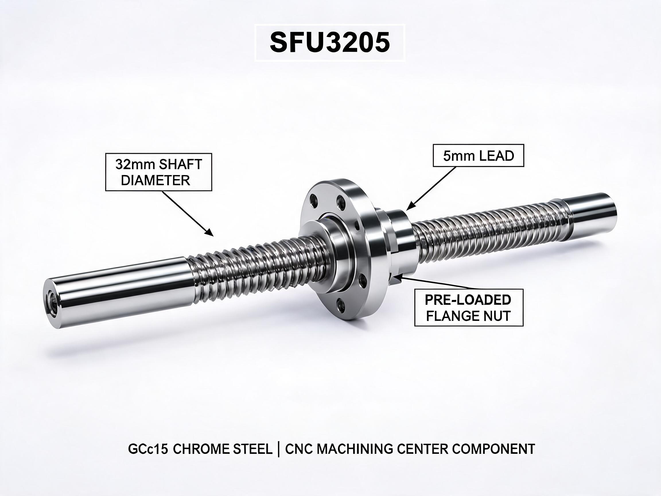
A larger shaft raises bending stiffness directly and keeps the axis simple — no added support hardware, no lubrication point, no extra alignment step. This is often the better trade when the whole axis is being specified fresh, when the stroke is long but not extreme, or when the thrust peaks are high enough that you want stiffness built into the shaft rather than assembled around it. A 32 mm rolled screw such as the SFU3205 heavy-duty rolled ball screw for CNC machining centers covers strokes up to 4000 mm with a BK32/BF32 end-block pairing, and its diameter does proportionally more for buckling than its dynamic rating alone would suggest.
For a shorter, precision-focused axis, a smaller ground screw may be the correct choice provided the stroke stays inside its range and the thrust profile is genuinely light. The SFE series ground ball screw assembly covers the 200–1200 mm stroke band with a 20 mm shaft and a double-nut dynamic rating of 12.7 kN. The decision is not which screw is better in general; it is whether the stroke, orientation and thrust peaks of this axis sit inside what the shaft can carry in compression.
The Highest-Risk Applications
Two profiles concentrate the risk.
Vertical axes. A vertical axis holding a load against gravity puts the screw in continuous compression during the hold and lift phases, and the load is present for long dwell periods rather than a brief peak. The compression load is not intermittent — it is the resting state of the machine. A screw that would be fine on a horizontal axis with the same rated load can be the wrong choice vertically.
Thrust-heavy presses. Presses and similar machines apply the highest axial force of any common ball-screw duty, often as a sharp peak rather than a smooth curve. The peak thrust is what drives the buckling check, not the average. Where the press has a long stroke, the two factors — high peak thrust and long unsupported length — combine at mid-stroke, which is exactly where the risk is greatest.
A long-stroke horizontal axis driving a heavy carriage under acceleration also belongs on the watch list, because the inertia force during acceleration and deceleration appears as axial compression and tension in the screw.
Pre-Order Checklist for a Long-Stroke Axis
Before placing an order, confirm these points with the supplier. They are the inputs that determine whether the selected screw is adequate as a column, not just as a nut-and-raceway assembly.
- Stroke. The full travel, not just the working range. Longer stroke means longer unsupported span and lower buckling resistance.
- Mounting orientation. Vertical, horizontal or inclined, and how long the axis holds load in each state. Vertical hold is the high-risk case.
- Thrust peaks. The maximum axial force in compression — including acceleration, deceleration, cutting or pressing peaks — not the running average.
- End machining. The exact end configuration required by the chosen support blocks, and whether the screw is supplied pre-machined to match them.
- Support block type. Which fixed and supported blocks are used at each end, and how rigidly each end constrains the screw. This sets the effective length the buckling check is based on.
- Straightness and mounting alignment. A screw has to be aligned to the axis, and the housing and nut must not introduce side loading that adds to the compression stress.
- Whether an intermediate support is possible. If the stroke is long and the thrust is high, ask early rather than after the axis is built.
If the supplier cannot state how the screw behaves in compression for your stroke, orientation and peak thrust, that is the question to press on — it is separate from the dynamic load rating.
What to Take Away
On a long-stroke axis, the dynamic load rating answers a different question from the one that will fail the machine. Buckling is a static compression limit on the shaft as a column, it is governed by diameter and end fixing, it becomes sudden when reached, and it is worst on vertical axes and thrust-heavy presses. Choose the shaft diameter and support arrangement against the real stroke and the real peak thrust, and the axis will behave the way the sizing assumed.
Sizing a specific axis? Send the stroke, mounting orientation, peak thrust and the end-block arrangement you intend to use, and we can work from those inputs rather than from the dynamic rating alone.