Ordering a custom ball screw starts with a complete specification: shaft length and diameter, end machining from your 2D drawing, nut and flange details, support block pairing, precision grade, material, and quantity. This checklist covers what suppliers need from you and when a custom length is truly necessary.
Start with the Drawing, Not the Catalog
If you cannot mount a catalog-length ball screw, you need a custom order. The specification that gets quoted and built is the one you put on paper. Before you send an RFQ, collect the facts below. A complete package reduces back-and-forth and gives the supplier what is needed to confirm feasibility, lead time, and price.
- Provide shaft length, diameter, and end machining details directly from your 2D drawing or DXF.
- Match the nut flange pattern and support blocks to your mounting interface before ordering.
- Choose rolled C7 or ground C5 based on travel accuracy needs, not on habit.
- Select GCr15 chrome steel or 9Cr18Mo stainless according to environment and cleaning requirements.
- Confirm MOQ and lead time early; custom end machining can change both.
Shaft Length and Diameter
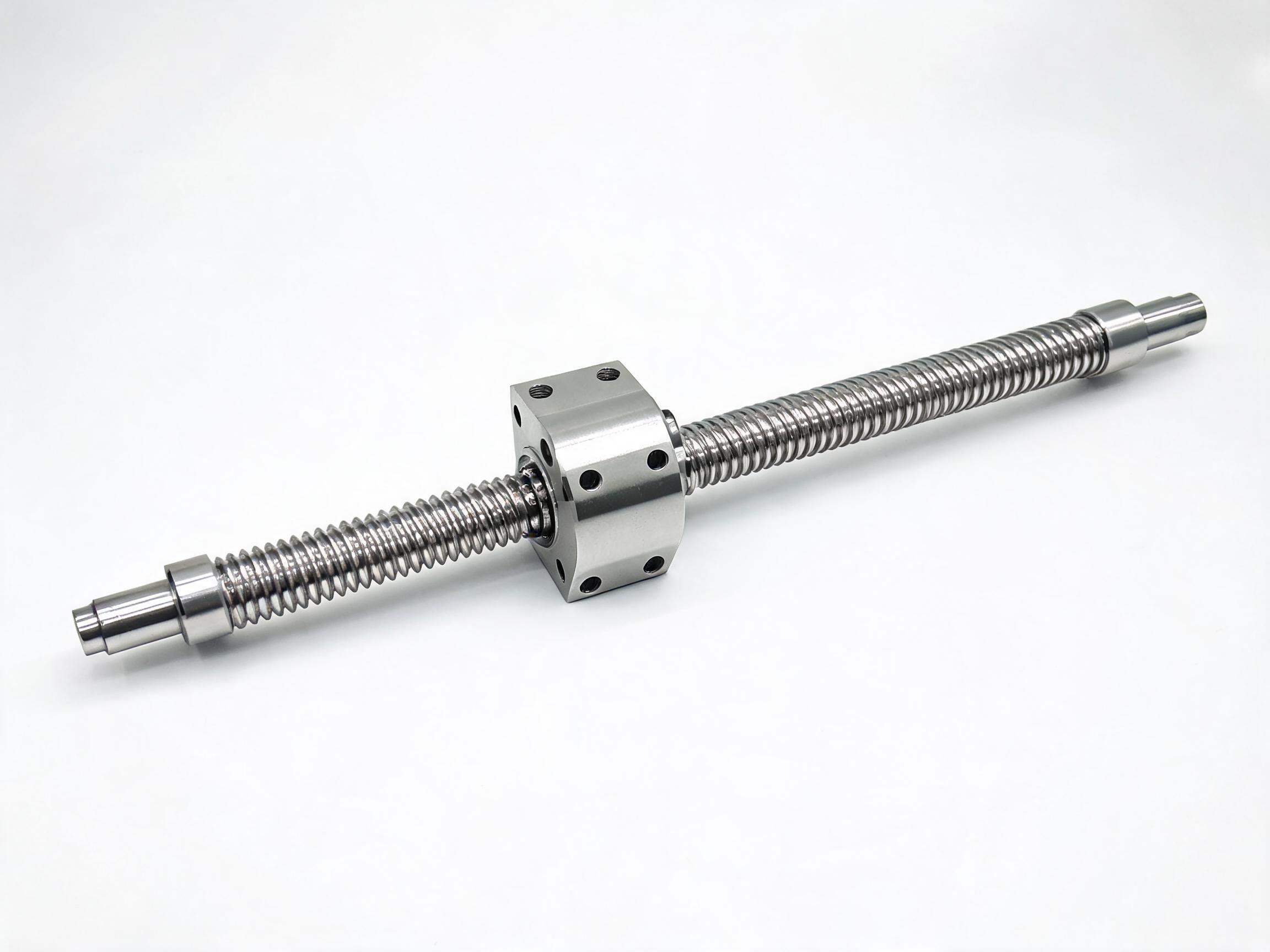
The shaft is the starting point. Specify the overall length, the thread length, and the shaft diameter. Standard SFU series rolled assemblies, such as the SFU1605, come in lengths from 300 mm to 1500 mm. The SFU2510 extends to 3000 mm. If your required length falls outside those ranges, or if you need a length that is not a catalog standard, you are ordering a custom length. State the length in millimeters and note whether it includes the end journals.
Custom lengths with special end machining typically take 15–25 business days. That figure assumes a complete, approved drawing. Incomplete drawings add review time. For a standard assembly, see the SFU Series Rolled Ball Screw Assembly range as a starting reference before deciding that a custom shaft is necessary.
End Machining Details from the 2D Drawing
End machining is where most custom orders succeed or fail. The supplier can adjust journal diameter, keyway, thread, and circlip groove to your drawing, but only if the drawing is clear and dimensioned. Include the following on the 2D drawing or DXF:
- Journal diameter and tolerance for each end.
- Keyway width, depth, and position relative to a datum.
- Thread specification (metric or imperial) and thread length.
- Circlip groove diameter, width, and location.
- Any flats, cross-holes, or special features.
- Datum and geometric tolerances that matter for assembly.
Do not rely on a sketch or verbal description for end machining. A dimensioned drawing is the only reliable way to confirm that the shaft fits your bearing blocks, coupling, and motor mount. If you have a 3D model, supply it alongside the 2D drawing, but the 2D drawing governs the machining dimensions.
Nut Type and Flange Pattern
The nut must match your mounting interface. Specify the nut type (single nut, double nut, flange nut) and the flange pattern: bolt circle diameter, number of holes, hole diameter, and thread depth. If you are using a standard flange nut, confirm that the bolt pattern matches your carriage. For a model with a defined flange, see the SFU2510 Rolled Ball Screw Assembly with Flange Nut. If your machine requires a non-standard flange, note that custom nut housing designs start from 200 pieces.
Also state the nut preload class if your application requires it. For many positioning tasks, a standard preload is sufficient, but high-rigidity axes may need a different class. If you are unsure, confirm with the datasheet or ask the supplier to recommend based on your axial load and speed.
Support Block Pairing
Support blocks fix the screw axially and radially. Specify the block model at each end. The SFU2510 is compatible with BK25 and BF25 blocks. For other diameters, confirm the matching block series. If you are designing a new machine, include the support block mounting dimensions in your drawing package so the supplier can verify that the end machining matches the block bore and shoulder.
If you plan to use blocks from another supplier, provide their datasheet or drawing. Mixing components from different sources is possible, but the interface dimensions must be checked. The supplier can machine to your drawing, but cannot guarantee fit with a third-party block unless the dimensions are supplied.
Precision Grade: Rolled C7 vs Ground C5
Precision grade affects travel accuracy and cost. Rolled C7 assemblies are common for general positioning. Ground C5 screws offer tighter lead accuracy and are used where travel error must be controlled more closely. The choice depends on your application:
| Grade | Typical travel error | Common use |
|---|---|---|
| Rolled C7 | ±0.05 mm/300 mm | General automation, transport, adjustment axes |
| Ground C5 | ±0.008 mm/300 mm | Precision positioning, machine tools, instruments |
Do not specify C5 by default. If your assembly can tolerate C7 error, rolled C7 is usually the lower-cost option. If your process requires C5, confirm that the support blocks and nut are compatible with that grade. For miniature applications, the BSH series miniature ground ball screw covers 6–12 mm shaft diameters and is available in C5 grade, with a 9Cr18Mo stainless steel option. See the BSH Series Miniature Ground Ball Screw for Precision Instruments for details.
Material Options
Material selection depends on environment and cleaning requirements. Standard screws are made from GCr15 chrome steel (52100 equivalent), induction hardened to HRC 58–62 on the ball track. This material is suitable for most industrial environments with proper lubrication. For corrosive or clean environments, 9Cr18Mo stainless steel is an option on the BSH series. Stainless steel resists corrosion but may have different load ratings; confirm with the datasheet.
If your application involves washdown, chemicals, or high humidity, specify stainless. If the screw will operate in a sealed, lubricated environment, GCr15 is typically sufficient. State the environment in your RFQ so the supplier can confirm material suitability.
Quantities and Lead Time
Quantity affects lead time and price. Standard length configurations carry a 50-piece MOQ per SKU, while custom end machining to your own drawing starts from 30 pieces. OEM laser-engraved part marking starts from 100 pieces. Custom nut housing designs start from 200 pieces. Plan your order quantity accordingly.
Lead time for custom lengths with special end machining is typically 15–25 business days after drawing approval. Larger quantities or complex features may extend that window; confirm at order. If you need a sample before production, discuss it with the supplier early.
What a Supplier Needs from You
To quote and produce a custom ball screw, the supplier needs:
- A fully dimensioned 2D drawing (PDF or DXF) with end machining details.
- Quantity per SKU and annual volume if available.
- Application description: load, speed, environment, duty cycle.
- Required precision grade and any preload specification.
- Support block model or interface dimensions.
- Any special marking or packaging requirements.
If you do not have a drawing, provide a sketch with dimensions and let the supplier confirm feasibility. However, production will not start without an approved drawing.
When a Custom Length Is Genuinely Needed
Before ordering a custom shaft, check whether a standard length can be adapted. Standard SFU assemblies cover 300–1500 mm (SFU1605) and up to 3000 mm (SFU2510). If your required length falls within those ranges and the end machining matches a standard configuration, a standard assembly may work. Custom length is necessary when:
- The required length is outside the standard range.
- The end machining does not match any standard option.
- The nut or flange pattern is non-standard.
- You need a specific material or precision grade not offered in the standard line.
In many cases, a standard assembly with modified end machining can be supplied, which may reduce lead time. Ask the supplier whether your requirement can be met by modifying a standard item.
Final Checklist Before You Send the RFQ
- 2D drawing or DXF with all end machining dimensions and tolerances.
- Shaft length, diameter, and thread specification.
- Nut type, flange pattern, and preload class.
- Support block model or interface dimensions.
- Precision grade (C7 or C5) and material (GCr15 or 9Cr18Mo).
- Quantity and any special marking or packaging.
- Application details: load, speed, environment.
With these details, the supplier can confirm feasibility, lead time, and price. For complex features, expect a drawing review before production. The goal is to specify once, correctly, so the screw fits your machine on arrival.