
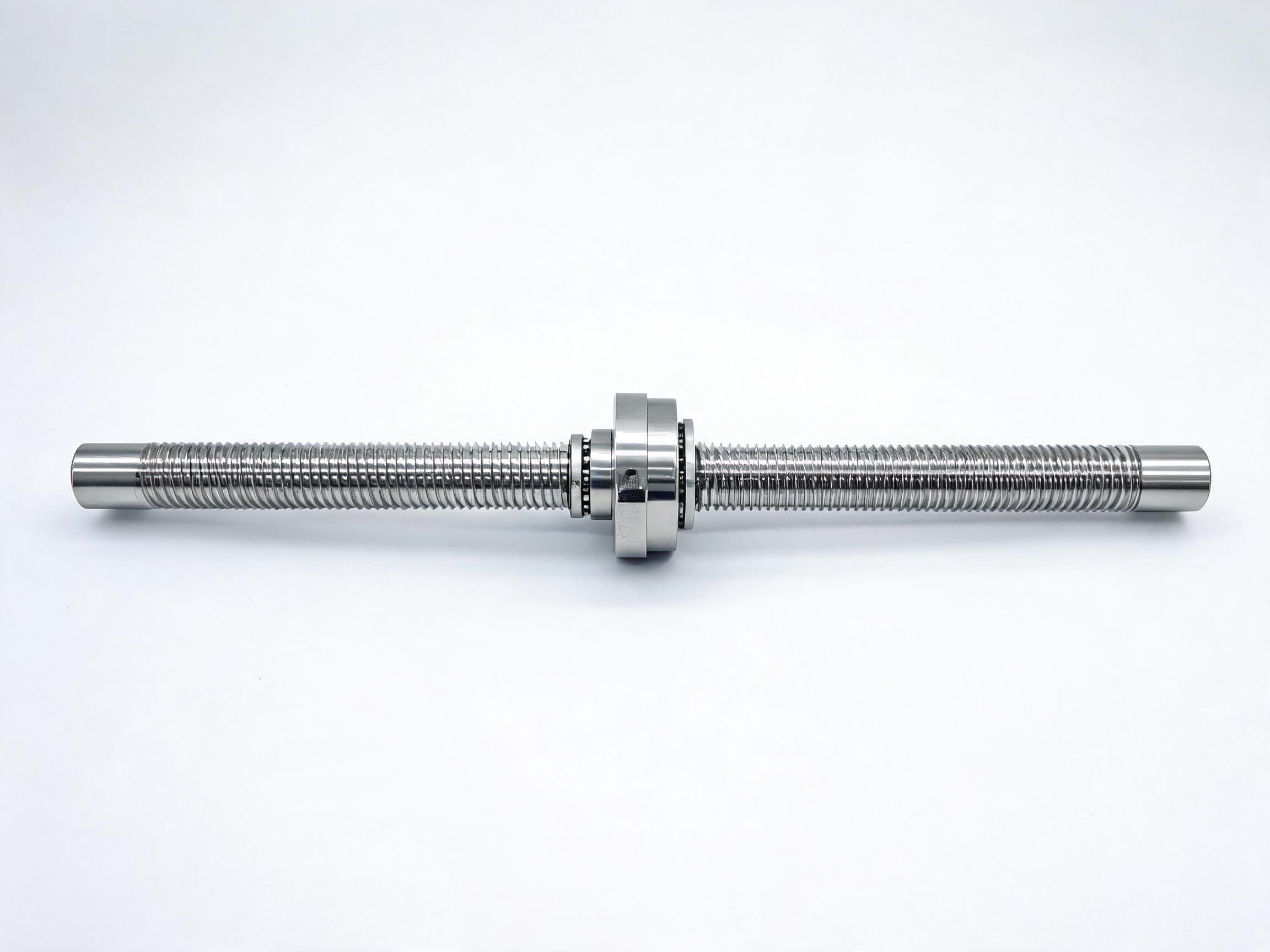
A practical guide for buyers connecting a motor to a ball screw assembly. It walks the drive-side mechanical chain interface by interface — coupling, mounting, support blocks, screw ends, nut — explains the flexible-versus-rigid coupling trade-off and fixed/floating support logic, and defines what 'assembly-ready' should mean on an order drawing.
The keyword search behind this article — ball screw assembly with motor — is usually made by an engineer or buyer who already has the screw and the motor and now has to join them. The questions that follow are always the same three: which coupling, how the motor mount works, and which support blocks. Handling them in order, interface by interface, avoids the most common outcome: a screw that arrives with ends machined to a different drawing than the one the coupling and bearing block were chosen for.
What this article covers
- The chain and the interfaces you have to own
- Motor-to-screw: selecting a coupling
- Flexible versus rigid: the real trade-off
- Support blocks: fixed versus floating logic
- Screw ends and nut housings
- What "assembly-ready" means on an order
- Specifications in this catalogue that anchor the discussion
The mechanical chain and who owns each interface
A driven ball screw is a sequence, not a single part: motor → coupling → support bearing block → screw → nut. Each arrow is an interface, and each interface has a different party responsible for getting it right. The motor is usually the buyer's own. The coupling may be buyer-supplied or chosen with the screw. The support blocks and screw ends are normally the screw supplier's responsibility, but only if they are specified correctly.
Failures at this level rarely come from the screw itself. They come from misalignment, from mismatched end machining, or from a bearing block model that does not match the shaft end provided. All three are decided before the order is placed, not during commissioning.
Motor-to-screw: how to select a coupling
The coupling sits between the motor shaft and the screw shaft and must transmit rotation while absorbing whatever small misalignment exists between them. It has two jobs, and they pull against each other: transmit motion faithfully, and tolerate imperfect alignment.
What to verify at this interface
- Bore diameters on both sides. The coupling must match the motor shaft and the machined screw end. If the screw end is machined to a drawing you have not shared, the coupling bore can be wrong before the parts arrive.
- Coupling type against alignment reality. A single-piece rigid coupling transmits exactly, but assumes the two shafts are already coaxial. A flexible coupling tolerates small offsets and angular error at the cost of a little torsional softness.
- Whether the screw end is keyed, clamped or plain. This affects how the coupling grips and how much torque can be transmitted without slipping. Confirm it against the drawing, not from the catalogue photo.
- Access for assembly. A coupling that cannot be assembled after the motor is bolted down is a coupling chosen too early. Check tool access before committing.
Flexible versus rigid: the trade-off in plain terms
Rigid couplings suit a configuration where the motor and screw are mounted on a single, well-machined housing and alignment is controlled by that housing. They transmit the most faithfully, but they will not forgive a shimmed motor or a housing bored slightly off-axis. They tend to load the support bearings harder if alignment is imperfect.
Flexible couplings (bellows, disc, or elastomer types) tolerate small parallel, angular and axial offsets. That tolerance is bought with a slight compliance in the drive, which matters in positioning work where the coupling is part of the measured chain. There is no universal correct answer — the choice follows from how much alignment confidence the mounting design gives you, not from a preference.
| Coupling type | Best suited to | What to confirm |
|---|---|---|
| Rigid (single-piece) | Motor and screw in one machined housing, alignment controlled | Shaft coaxiality; grip method on both ends |
| Flexible, bellows/disc | Separate motor mount, some shimming or angular error | Acceptable offset range for the coupling; torsional stiffness relative to the task |
| Flexible, elastomer | General transfer with modest precision demand | Whether the tolerance for torsional wind-up suits the positioning requirement |
Torque, speed and sizing of the coupling are project-specific. This article does not set those figures; they must come from the coupling and motor datasheets and the actual load case. Where a value is not supplied, refer to the datasheet.
Support blocks: fixed and floating logic
At the drive end, the screw is usually held by a support bearing block on each side. The logic is simple but easy to specify wrongly: one end is fixed (it holds the screw axially as well as radially), and the other is floating (it supports radially and allows axial movement as the screw expands or contracts).
If both ends are specified as fixed, the screw has nowhere to move axially and the thermal change has to go somewhere — usually into the bearing preload and the drive. If both ends are floating, the screw can walk axially under load. The pairing is what matters, and the block models must match the shaft ends the supplier machines.
How this connects to the motor mount
The fixed end is normally on the drive side, next to the motor. That makes the fixed block the reference plane for the whole chain. When you specify the motor mount, specify it relative to that block face, not to the end of the table or housing. A motor mounted to a different datum introduces an alignment error that none of the couplings can absorb indefinitely.
The block model and its matching shaft end are a set. In this catalogue, the SFU1605 rolled assembly is prepared for standard BK12/BF12 support blocks, and the heavier SFU3205 series uses BK32/BF32 compatible support blocks. Those model references are the anchor for ordering; the shaft end machining has to match the block you select.
Screw ends and nut housings: the two places orders go wrong
There are two components in the chain that are not the screw itself but decide whether the assembly bolts together: the end machining and the nut housing.
Shaft end machining
The screw ends are machined to a drawing — journal diameter, length, keyway or thread, and the bearing seat. That drawing must be agreed before manufacture and must match the coupling bore on the motor side and the block bore on the support side. If the drawing is silent, ask for the machined-end drawing and check it against your coupling and block datasheet.
Nut housing
The nut must bolt to the moving element. The flange pattern is the fixed fact: for the SFU1605 assembly the single flange nut has a four-hole M4 pattern, which fixes the nut housing and the bolt pattern the moving carriage must accept. Confirm the housing model and the flange pattern together, because a nut housing that does not match the carriage is a late-discovered problem.
What "assembly-ready" should mean on your order
A screw described as ready to mount should come with the shaft ends machined to the agreed drawing and the nut fitted, configured so it mounts directly on standard support blocks — so that the buyer's work is assembly and alignment, not re-machining. Whether the support blocks and nut housings themselves are included in the assembly quotation or ordered as separate items is a supply-scope point to confirm line by line on the quotation.
For the SFU1605 rolled assembly, that is the specification: it ships complete with both shaft ends machined, a pre-loaded single flange nut fitted, and it is ready to mount with standard BK12/BF12 bearing blocks and SFU1605 nut housings. The listed accuracy is C7 with ±0.05 mm/300 mm and a dynamic load rating of 6.8 kN for the single nut. Those are the catalogue values you can quote against; they are not a statement about how your particular motor and load will perform.
Where backlash matters, the DFU double-nut series is the relevant option: a zero-backlash double nut with axial backlash under 0.003 mm, available in precision grades P0/P1/P2. See the DFU double-nut zero-backlash ball screw range for the grade and configuration detail. For the rolled assembly with fitted nut and machined ends, see the SFU series rolled ball screw assembly page.
Pre-order checklist
- Coupling: bore on motor side, bore on screw side, grip method, flexible or rigid — all confirmed against the shaft end drawing.
- Motor mount: is the motor referenced to the fixed bearing block face?
- Support blocks: fixed on the drive end, floating on the opposite end, and the block model matches the machined shaft ends.
- Shaft ends: machined-end drawing agreed and available before manufacture.
- Nut housing: flange pattern matches the carriage (four-hole M4 for the SFU1605 single nut).
- Supply scope: confirm whether the support blocks and nut housings are included in the assembly quotation or ordered separately.
- Any value not on the drawing: request it from the datasheet before the order is placed.
Frequently asked questions
Can I use my own coupling with a supplied assembly?
Yes, but only if the machining on both shafts matches the coupling bore. Send the coupling drawing before the screw end is machined; the screw end is difficult to change after the fact.
Do I need a fixed and a floating block, or two fixed blocks?
Normally one fixed block on the drive end and one floating on the opposite end, so the screw can move axially as it warms or contracts. Two fixed blocks confining the screw is a specification to confirm deliberately, with the supplier, against your application.
When is the double-nut series worth considering?
When backlash in the nut affects the positioning requirement. The DFU double-nut series lists axial backlash under 0.003 mm and is specified in P0/P1/P2 grades; the grade you need depends on the task, and that is a point to confirm rather than assume.
What if the datasheet does not list my motor shaft size?
Then the coupling bore is not confirmed. Refer to the coupling datasheet and the machined-end drawing together, and confirm the match with the supplier before ordering.
Next step
If you are specifying a ball screw assembly with motor, send the motor shaft diameter, the required nut housing pattern, and the fixed-end block model you intend to use. With those three inputs, the machined-end drawing and the assembly-ready configuration can be fixed before manufacture rather than after delivery.