
A practical guide to sizing and fitting a ball screw brake on a vertical axis: why the load must be held on power loss, where the brake sits in the drive train, how to match holding capacity to the load with a safety margin, and what to check at installation and sign-off.
On a vertical axis, a ball screw brake is the component that decides what happens to the load when power disappears. This guide covers why the brake is needed, where it sits in the drive train, how to match holding capacity to the load with a safety margin, and what to verify at installation and checkout.
Key takeaways
- A vertical ball screw is usually non-self-locking: the screw can be back-driven by the load, so a holding brake is a machine-safety decision, not an accessory.
- Brake location depends on brake type — pre-motor, motor-mounted, or acting on the screw — and each puts different loads on couplings, keys and threads.
- Holding capacity must reflect the whole vertical load, with a safety margin set by your risk assessment; the actual torque and force figures come from the supplier datasheet.
- Screw friction torque feeds into the sizing, so preload and backlash choice on the nut matter as much as the brake itself.
In this article
- Why a vertical axis needs a holding brake
- Where the brake sits in the drive train
- Matching holding capacity to the load and safety margin
- How the ball screw choice affects brake sizing
- Installation and checkout points
- Brake selection checklist
Why a vertical axis needs a holding brake
A horizontal ball screw only has to move mass across a surface. A vertical ball screw also has to resist gravity, and when the motor is de-energized the load becomes a stored force acting back on the screw. Unless the screw and nut combination is self-locking — and a low-friction ball screw generally is not — the load can drive the screw backwards. That means the axis can move down under its own weight when power is lost, when a drive faults, or when the servo is disabled during maintenance.
The consequences depend on the machine. A tool spindle that drops onto a workpiece, a load that sinks onto a lower stop, or a lift that creeps down overnight are all failures of holding, even if nothing breaks. A holding brake addresses the uncontrolled drop; it is distinct from a dynamic brake, which stops a moving load and which is normally handled by the servo drive and its resistor. Buyers searching for a ball screw brake usually want the holding function: keep the load where it is when the machine is at rest or unpowered.
This also shapes what the brake is for. It is not there to decelerate a moving axis in normal production, and treating it as a stopping brake puts wear on the brake and shock into the drive train. The common arrangement is to engage the brake when the axis is stationary or nearly stationary, and to release it only after the drive has taken up the load. Confirm the intended function with the machine builder's control sequence, because the brake hardware and the control logic have to agree.
Where the brake sits in the drive train
There is more than one valid position for a holding brake, and the position changes what the brake has to hold. Three arrangements are typical.
- Motor-mounted holding brake. The brake is inside or on the servo motor shaft. It holds the motor rotor, and the motor, gearbox and screw transmit the holding torque to the load. Any backlash or compliance between the motor and the screw appears as movement when the brake engages.
- Brake on the screw or gearbox output. The brake acts closer to the load. It holds the screw directly, so coupling backlash and gearbox backlash do not open up a drop path — but the brake must generate a larger torque because it no longer benefits from gear reduction.
- External or fail-safe brake on the load side. Used where the load path demands a positive hold independent of the motor, for example a separate caliper or drum arrangement on the axis mechanism.
For most servo-driven vertical axes with a screw and a planetary gearbox, the motor-mounted brake is the default, and the reduction ratio keeps the required brake torque manageable. The trade-off is that every compliant element between the rotor and the load — coupling backlash, keyed connections, gearbox backlash — can show as a small downward step when the brake sets. On a precision axis this matters. If you cannot accept that step, the brake position has to move closer to the load, and the torque requirement grows accordingly.
Two details follow from this. First, the holding torque at the brake must be translated to holding force at the load through the full drive train, and the translation has to account for screw lead, gear ratio and efficiency. Second, the brake position determines the coupling and screw selection: a brake that holds the screw shaft directly puts a torsional load on that shaft and on any keyway or clamping element, so those parts need to be rated for it. The brake supplier datasheet is the source for brake torque and response time; the screw supplier data is the source for lead, preload and friction torque. The two have to be brought together before the axis can be declared safe.
Matching holding capacity to the load and safety margin
Sizing a holding brake starts with the actual vertical force at the screw, not the motor's rated torque. The vertical load — moving mass, tooling, any counterweight or spring balance — times the screw lead and the drive efficiency gives the torque the screw needs to resist during a hold. A gearbox reduction then divides that value down to the torque at the brake shaft.
Several factors are easy to leave out: friction in the screw (which helps hold, but cannot be counted on), preload drag, the weight of the screw and coupling themselves, and any unbalanced air or hydraulic force on the axis. Each has to be identified rather than assumed. Missing one can produce a brake that holds in a test but creeps under load.
The safety margin is a decision for the machine's risk assessment, not a catalogue default. It depends on whether the axis sits over people, what the consequence of a drop is, whether the brake is checked regularly, and how the brake is used in normal operation. The point for a buyer is that the margin should be stated as a requirement — for example, the required holding torque at the brake shaft for the worst-case load — and the brake chosen against that figure with the supplier's data. Do not size by the nominal motor rating, and do not assume the brake can also serve as an emergency stop.
Where numbers come from
Holding torque, release voltage, response time and wear limits are brake-specific. They must be confirmed on the supplier datasheet and verified against the worst-case load calculation. Any figure quoted in an early conversation is a planning input, not a guarantee of holding force.
How the ball screw choice affects brake sizing
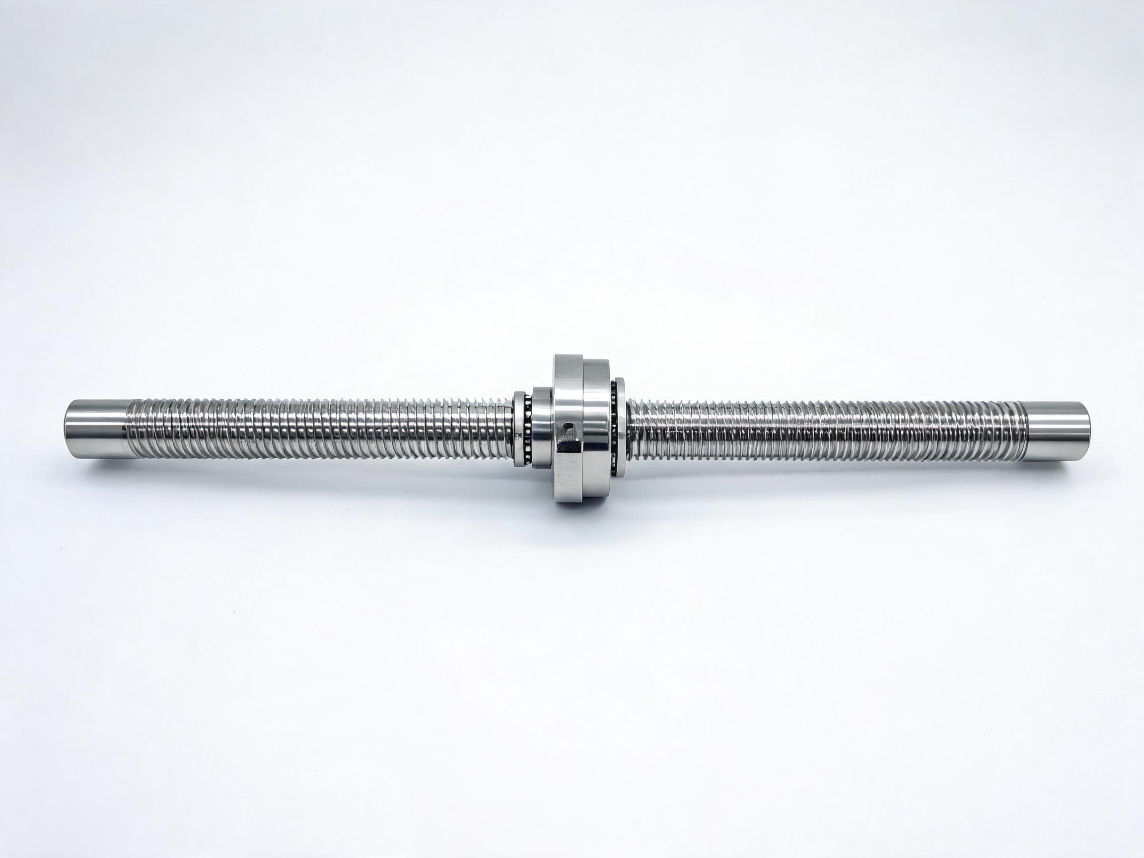
Two product families we manufacture illustrate the trade-offs a vertical axis buyer faces. The DFU series double-nut zero-backlash ball screw uses a double nut to keep backlash below 0.003 mm and carries 1.5x the load of an equivalent single nut, in sizes 16–40 mm with precision grades P0, P1 and P2. On a vertical axis the 1.5x load capacity gives headroom against the vertical force, and the very low backlash means the drop path through the nut is small. For a precision spindle or measuring axis where a post-brake step is unacceptable, this reduces how much of the drop comes from the nut itself.
The SFU series rolled ball screw assembly is a C7-grade rolled screw at ±0.05 mm per 300 mm, in lengths 300–1500 mm with HRC 58–62 hardened shaft. Rolled screws have higher friction drag than ground, preloaded screws, and that friction contributes to holding force. But friction cannot be counted as part of the safety margin, because it varies with lubricant, temperature and wear. The brake must still hold the load on its own.
| Selection factor | Effect on brake sizing | What to check |
|---|---|---|
| Screw lead | Longer lead means less torque per unit of vertical force | Confirm lead on the datasheet before calculating |
| Nut preload and backlash | Higher preload adds drag; lower backlash reduces the drop path | Check backlash rating and preload figures for the chosen grade |
| Gearbox ratio | Reduces required brake torque; adds backlash | Get the exact ratio and torsional backlash |
| Coupling backlash | Shows as a step when the brake sets | Specify your allowable hold step and verify against it |
| Brake type and position | Sets the torque the brake must generate and where it acts | Confirm the brake datasheet and the drive train it acts through |
Installation and checkout points
Installation errors on a holding brake are less about the brake itself than about the elements around it. The following checks are worth walking through before sign-off.
- Mounting and release. Confirm the brake is fully released before the motor takes load, and that release current is within the brake ratings. A partially released brake drags and overheats.
- Coupling and keyed connections. Check for the backlash and run-out you specified, because every gap here appears as a hold loss.
- Screw support and alignment. Misalignment increases friction drag and can tilt a preloaded nut, changing what the load does to the screw.
- Wiring and control sequence. Verify the brake engages on power loss and that the sequence never lets the drive disengage before the brake sets.
- Holding test. With the axis loaded, de-energize and confirm the load does not move beyond your stated allowance. Record the result at the load used.
The holding test is a record of that test under its conditions, not a blanket guarantee that the axis holds at every load and temperature. Where the risk assessment requires it, repeat the check with the worst-case load and record it alongside the brake datasheet and the screw specification.
Brake selection checklist
Bring the following to a supplier and the sizing conversation becomes concrete rather than approximate.
- Orientation and worst-case vertical load, including tooling, attachments and counterweights.
- Required hold at the load, as a torque or a vertical force, and the allowable drop step.
- Brake function: holding only, or dynamic use, with the control sequence that goes with it.
- Screw model, lead, accuracy grade and backlash/preload figure — the DFU series or the SFU series, or another specified assembly.
- Gearbox ratio and couplings, and the backlash budget in the drive train.
- Safety margin or classification required by the machine's risk assessment.
- Environment and duty: temperature, lubricant, expected engagement frequency.
With these in hand, the brake, screw and gearbox can be compared on the same requirement rather than on separate catalogues. Where any figure is open — brake torque, reaction time, allowable wear — leave it open and ask for the datasheet value; a filled-in number from memory is not a substitute.
The DFU series has a minimum order quantity of 20; the SFU series has a minimum order quantity of 50. Brake torque, holding force, response time and safety margin values for a specific build must be confirmed with the supplier datasheet before the axis is signed off.