A practical guide to the drawing and CAD package buyers should request before ordering a ball screw: shaft-end machining, nut flange hole patterns, support bearing fits, a pre-order checking list, and the formats and custom end-machining workflow worth confirming with your supplier.
Procurement Guide
A ball screw CAD model or drawing is not decoration for a datasheet. It is the document that lets a machinist cut the shaft ends, a designer place the nut flange holes, and a buyer check that the part arriving on the dock will actually bolt into the machine. This guide explains what belongs in a drawing package you can use for both RFQ and assembly, and what to ask a supplier for before the order is placed.
Key takeaways
- A usable package covers shaft-end machining, nut flange hole positions, and support bearing fits — not just the nominal diameter and lead.
- For SFU-series rolled screws, end machining can be adjusted to your drawing (journal diameter, keyway, thread), so send a 2D drawing or DXF with the inquiry.
- Match the drawing accuracy grade to the job: C7 for general positioning, C5 grinding grade where tighter tolerance is specified.
- Confirm the drawing revision and units before production; the version that gets made is the version you sign off.
What a ball screw drawing package should contain
When buyers search for a ball screw CAD model, they usually need one of two things: a file to drop into a machine layout, or a drawing to send out for quotation. The two overlap, but a supplier-quality drawing must carry machining detail that a generic CAD block often leaves out. A complete package typically covers three areas.
1. Shaft-end machining
- Journal diameters and lengths at each end, with tolerances, so the end can be turned to fit the bearing or coupling.
- Keyways — width, depth, length and position, if a pulley or gear is keyed to the shaft.
- Threaded ends — thread size, pitch, length and the locknut or preload nut that will sit on it.
- Shoulders and undercuts that locate bearings and set axial position.
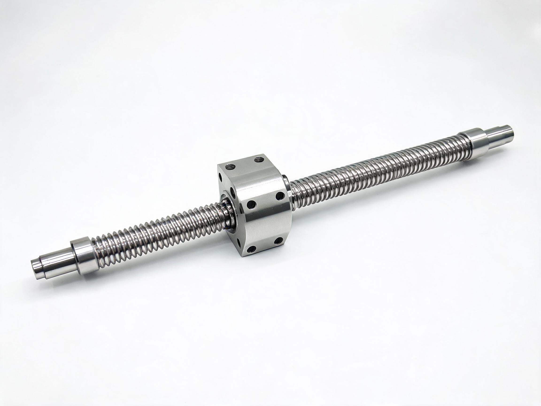
On rolled screws such as the SFU series rolled ball screw assembly, end machining can be adjusted to the customer drawing, including journal diameter, keyway and thread. That is why the drawing, not just the model number, drives the quote.
2. Nut flange hole pattern
The nut is the half of the assembly that bolts to the moving carriage. The drawing should show:
- Flange outline and overall dimensions.
- Hole count, diameter, spacing and bolt circle.
- Any counterbore or spot-face details.
For reference, the SFU1605 nut uses a four-hole M4 flange and is compatible with common SFU1605 nut housings on the market. If your carriage is already drilled, compare its hole pattern against the drawing before ordering — a match on diameter and lead does not guarantee a match on flange holes.
3. Support bearing and end-support fits
Fixed and floating end supports locate the screw and take axial load. The drawing should state the bearing bore the shaft end is machined to fit, plus the housing interface. The SFU1605, for example, is suited to BK12/BF12 end supports. Get the support unit part number onto the drawing so the machinist works to the right fit rather than a nominal size.
Reading the numbers a drawing should carry
A drawing is only as useful as the parameters printed on it. For a screw in the SFU family, a typical specification line looks like this:
| Item | Typical value (SFU1605 example) | Why it matters on the drawing |
|---|---|---|
| Nominal diameter / lead | 16 mm / 5 mm | Sets the nut size and travel per revolution |
| Accuracy grade | C7, ±0.05 mm/300 mm | Lead accuracy over a defined length |
| Material / hardness | GCr15, HRC 58–62 | Informs machining and handling notes |
| Dynamic load rating | 6.8 kN | Load basis for selection |
| Standard length range | 300–1500 mm (longer on request) | Determines whether the length is standard or custom |
The 16 mm diameter and 5 mm lead in SFU1605 are designations, not a measurement certificate. Always check the machined end dimensions and the overall length on the drawing against the space you have.
When you need a grinding-grade drawing
If the application calls for tighter lead accuracy than C7, the drawing should specify a ground screw. The SFE series ground ball screw assembly is rated C5, ±0.008 mm/300 mm. That level of accuracy changes what the drawing must show: the accuracy grade, the reference length over which it is measured, and the inspection basis all need to be stated. Quote requests that leave the grade blank often come back with a default, so put the grade on the drawing yourself.
Similarly, if the design needs zero-backlash positioning, the DFU series double-nut zero-backlash ball screw uses a double nut with backlash under 0.003 mm. On the drawing, the nut length and preload adjustment access should be dimensioned, because a double nut is longer than a single nut and may not fit the same space.
Formats to send and request
For an RFQ, a clean 2D drawing or DXF is the most reliable input. Confirm what your supplier can open:
- 2D drawing (PDF or DWG) for the shaft ends, flange holes and fits.
- DXF for the profile and hole positions when the supplier needs to program machining.
- 3D CAD model (STEP is common) for design layout — useful for checking clearance, but it should agree with the 2D drawing.
When you request a CAD model from a supplier, ask whether it is a generic catalog model or one built from the actual machined drawing. A catalog block reflects the standard part; it will not show your custom journal, keyway or thread.
Pre-order checking list
Before releasing a purchase order, walk through these points against the drawing:
- End machining matches the bearing and coupling — journal diameters, lengths and fits.
- Flange holes match the carriage — count, diameter, spacing and bolt circle.
- Threaded ends match the locknuts you intend to use.
- Overall length and travel fit the machine envelope, including support units.
- Accuracy grade is stated (C7 or C5) and matches the application.
- Revision and units are marked; metric and inch mix-ups are a common source of rework.
- Inspection points are agreed — what will be measured and recorded.
Put the same details in the RFQ that you put on the drawing. If the drawing and the RFQ text disagree, ask the supplier which they will work to.
Custom end-machining workflow
A typical custom order runs in this order:
- Send the 2D drawing or DXF with the inquiry; include quantity, length and accuracy grade.
- Supplier reviews the drawing and confirms what can be machined to your specification.
- Quotation and drawing confirmation; clarify any dimension that cannot be met.
- Machining to the approved drawing, then inspection and packing.
For the SFU series, the minimum order quantity is 50 pieces. Standard lengths ship in roughly 7–15 working days; custom machining takes about 15–25 working days. Treat those figures as indicative and confirm the schedule on the order confirmation.
FAQ
Can I get a CAD model directly from the supplier?
Ask what is available for your model and for your specific end-machining. A catalog CAD model gives the standard outline; a drawing-matched model or 2D drawing is what you need to verify the actual machined ends.
Is a 2D drawing or a 3D model better for an RFQ?
For machining and quoting, a 2D drawing or DXF carries the dimensions, tolerances and fits the machinist needs. A 3D STEP model helps with layout and clearance checks. Send both when you have them, and keep them consistent.
What if my carriage holes do not match the standard flange?
Compare the hole count, diameter and spacing on your carriage against the drawing before ordering. The SFU1605 four-hole M4 flange is compatible with common SFU1605 nut housings, but a non-standard carriage should be confirmed against the drawing first.
What should I send with the first inquiry?
The drawing or DXF, the model and accuracy grade, the overall length, the end-support part numbers, and the quantity. That set lets the supplier quote against what you will actually build.
Drawings drive the quote, so the version you approve is the version that gets made. Confirm revisions, units and inspection points before production starts.