
A practical method for pairing a stepper or servo motor with a rolled ball screw. It shows how lead converts motor torque into thrust and motor RPM into linear speed, then walks through a four-step matching check covering thrust, speed, duty and alignment, before explaining when a fine lead beats a coarse one.
Selection guide
A ball screw does not decide on its own whether a motor is strong enough or fast enough. The lead does. Once you write the two conversion relationships down, most mismatches show up before anything is ordered.
In this article
- How lead converts torque into thrust
- How lead converts RPM into linear speed
- A four-step matching check
- Fine lead versus coarse lead
- What to confirm with the supplier
Two relationships do most of the work
Lead is the distance the nut travels in one full turn of the screw. Every other question about motor matching follows from that single number.
Speed. Linear speed is the product of rotational speed and lead:
linear speed = RPM × lead
At 600 RPM, a 5 mm lead gives 3,000 mm/min. The same motor on a 10 mm lead gives 6,000 mm/min. The motor has not changed; only the conversion ratio has.
Force. Thrust is torque divided by the lever the lead creates, with losses applied:
thrust ≈ (2π × torque × efficiency) / lead
For the same motor torque, halving the lead roughly doubles the available thrust, and doubling the lead roughly halves it. That is the core trade-off behind every ball screw motor pairing.
Two cautions matter here. First, efficiency and friction losses are not a constant you can assume; the numbers you use must come from the screw and nut datasheet, along with the preload and lubrication condition being quoted. Second, a motor's rated torque is a starting point, not a guarantee across its whole speed range, so the thrust available at the speed you actually run at is the figure that counts.
Step 1: Fix the thrust requirement first
Start from the load, not from the motor. Add up the moving mass, the cutting or pressing force the axis must deliver, and the gravity component if the screw is vertical. Then add margin for acceleration, since accelerating a mass demands extra force beyond holding it.
The screw's own dynamic load rating sets the mechanical ceiling. An SFU series rolled ball screw assembly reaches 6.8 kN dynamic load on the SFU1605 single nut, and the SFU2510 carries 17.2 kN. Those ratings describe the screw and nut, not the motor. A motor that cannot supply the torque for your thrust target will stall long before the screw is the limit.
Work backwards: required thrust, divided by the lead relationship above, gives the torque you need at the nut. Then allow for everything between motor and nut.
Step 2: Cap the linear speed
Take your required traverse speed and divide by the lead to get the motor RPM:
RPM = linear speed / lead
This is where stepper and servo behaviour diverge, and the difference is qualitative rather than a matter of specific curves here. A ball screw stepper motor setup is simpler to drive and holds position without an encoder, but available torque falls as step rate rises, so a high-RPM requirement can push a stepper outside its comfortable region. A servo is closed-loop and better suited to sustained high speed and to loads that vary during the move.
There is also a mechanical limit on the screw side. Critical speed and nut speed ratings come from the screw datasheet and depend on length and mounting; a short 5 mm lead screw run at high RPM may exceed its critical speed, while a 10 mm lead reaches the same linear speed at half the RPM.
Noise is a practical check as well. The SFU1605 is bench-measured at typically below 55 dB at 600 RPM; running faster changes that picture, so ask for data at your actual operating point rather than extrapolating.
Step 3: Check duty cycle and inertia
- Duty cycle: continuous high-speed operation heats a motor differently from short indexing moves. State your duty pattern when asking for a motor recommendation.
- Reflected inertia: the screw's inertia, plus the load's, appears at the motor shaft scaled by the lead. A coarse lead reflects more inertia back to the motor, which affects acceleration and tuning.
- Holding: a vertical axis needs either a motor that holds torque when stopped or a brake. This is a motor selection question, not a screw one.
- Resolution: linear resolution equals motor resolution per revolution multiplied by lead and divided by any reduction. A 5 mm lead gives finer positioning per step than a 10 mm lead on the same motor.
Step 4: Coupling and support bearing alignment
Motor matching fails at the joint as often as in the calculation. Check these before ordering:
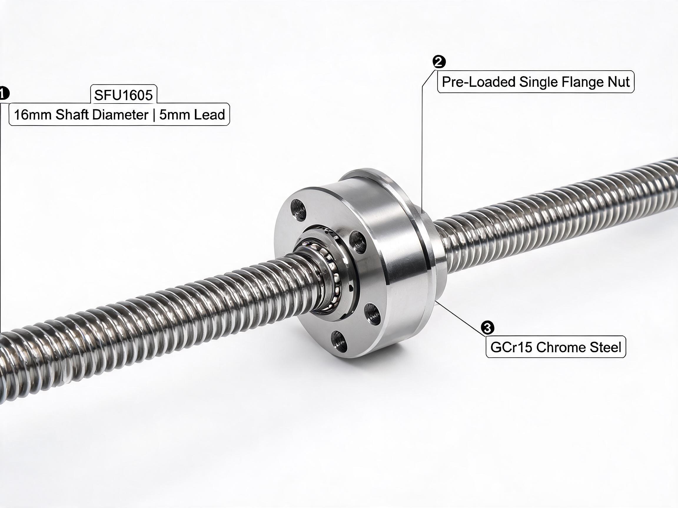
- Does the screw arrive end-machined to suit your coupling and bearing blocks? The SFU1605 ships end-machined with a preloaded single flange nut, ready for BK12/BF12 support blocks, so confirm your motor shaft and coupling match that journal.
- Is the coupling rated for the torque and speed, and does it tolerate the small misalignment between motor and screw? A rigid coupling transfers misalignment into the bearings.
- Are the support bearings fixed at one end and floating at the other, so thermal growth does not load the motor bearing?
- Is backlash acceptable? Where positioning repeatability matters in both directions, a DFU series double-nut zero-backlash ball screw removes axial play in the nut; the DFU2005 is rated 10.2 kN dynamic, with shaft sizes from 16 to 40 mm and leads of 5, 10 and 20 mm across the series.
Fine lead or coarse lead
| Requirement | Fine lead (e.g. 5 mm) | Coarse lead (e.g. 10–20 mm) |
|---|---|---|
| Thrust for a given motor torque | Higher | Lower |
| Linear speed for a given RPM | Lower | Higher |
| Linear resolution per motor step | Finer | Coarser |
| Backdrive risk on vertical axes | Lower | Higher |
| Typical fit | Pressing, clamping, precise positioning | Fast traverse, long travel, lower force |
Fine lead wins when force and resolution dominate: a small motor driving a press or a positioning axis where each step must be short. Coarse lead wins when the axis mostly travels: a long gantry or a pick-and-place that must cover distance quickly, with modest force demands. If you need both, a reduction between motor and screw changes the balance, at the cost of speed.
What to confirm with the supplier
The calculation gets you close; the supplier's data closes the gap. Bring these to the conversation:
- Efficiency and friction figures for the specific screw, nut and preload you are buying, so the thrust calculation is not built on an assumed constant.
- Critical speed and permissible nut speed for your screw length and mounting arrangement.
- Dynamic and static load ratings for the exact nut variant, since single and double nuts differ.
- The end-machining drawing, so the motor shaft, coupling and bearing block are checked against real dimensions rather than nominal ones.
- Any measured noise or running data at your operating RPM, to confirm the axis meets site requirements.
A useful shortcut: give the supplier your thrust target, maximum linear speed, duty pattern and mounting orientation. With those four inputs, the lead and the motor size can be checked against each other before a purchase order exists, which is far cheaper than discovering the mismatch during commissioning.