
A practical measurement checklist for maintenance engineers replacing a worn ball screw. Covers the five dimensions that must match, how to read the old screw, rolled versus ground grade selection, support block and end-machining details, backlash and reversal checks, plus a copyable pre-order list.
A ball screw that arrives with the right part number can still refuse to go into the machine. The part number identifies a family, not a fit. What actually determines whether a replacement drops in is a short list of measurements taken from the screw you are removing, plus the drawing that defines how its shaft ends were machined. This article walks through that measurement sequence so the order you place matches the machine on the floor.
Key takeaways

- Five dimensions decide fit: nominal diameter and lead, overall length, end-journal machining, support block series, and nut flange hole pattern.
- Measure the old screw at the journals and confirm lead by counting turns over a known travel, not by trusting a label.
- A C7 rolled screw is the correct replacement for many general-positioning machines; a C5 ground screw is needed where the machine's accuracy budget requires it.
- Journal dimensions and accuracy grade should be confirmed against a drawing or datasheet before the order is released.
Why a replacement ball screw fails to fit even when the part number matches
Part numbers in ball screw catalogs usually describe the screw body: diameter, lead, and sometimes the nut style. They rarely capture the shaft ends, which are machined to suit a specific bearing block and coupling. Two screws with the same nominal size can have different journal diameters, different thread lengths, and different overall lengths. Any one of those differences stops the installation.
The five dimensions that must match are:
- Nominal diameter and lead. For example, a 16 mm shaft with a 5 mm lead. If either changes, the nut, the support blocks, and the machine's motion per revolution all change with it.
- Overall length. Measured end to end, including any threaded or stepped sections. A screw that is 10 mm short will not reach the supported-side bearing.
- End-journal machining. The diameter, length, and shoulder position of each machined end where it enters the bearing block, plus any keyway or thread for the locknut.
- Support block series. A BK12 fixed-side block and a BF12 supported-side block accept specific journal sizes. A screw machined for BK12 will not seat in a different series without re-machining.
- Nut flange hole pattern. The bolt circle and hole spacing on the nut flange must match the bracket that carries it. A four-hole M4 pattern is common on smaller screws, but the spacing still has to be checked.
When any of these is uncertain, the safe move is to send the old screw's drawing or a dimensioned sketch with the inquiry. A supplier can then confirm whether a standard assembly matches or whether the end machining needs to follow the buyer's drawing.
How to read the old screw before ordering
Reading the old screw means measuring the features that contact other parts, not just the screw body. Work from the shaft ends inward.
Measure the shaft ends
- Record the journal diameter at each end with a micrometer, at two positions 90 degrees apart, to catch out-of-round wear. A caliper is not adequate for journal diameters, because a journal that has to seat in a bearing block is specified in microns and a caliper resolution is coarser than that.
- Record the journal length from the shaft end to the shoulder.
- Note any thread at the end (for a locknut), its size and pitch, and any keyway width and depth.
- Measure the overall length from end to end.
Check for step wear
Wear does not appear evenly along a ball screw. The ball track usually shows a step where the nut spends most of its travel. Run a finger or a straight edge along the track and compare the loaded zone with the less-traveled ends. A visible step or a change in feel indicates the track has worn and the screw should be replaced rather than re-balled. Because feel is not a measurement, treat the track as suspect and have the wear depth verified by the supplier with a profile measurement before committing to a replacement. Also check the journal surfaces for scoring or fretting, because a worn journal can cause runout even with a new screw.
Confirm lead by counting turns over a measured travel
The lead is the axial distance the nut moves in one full revolution of the screw. To confirm it, mark the screw and the nut, rotate the screw exactly ten turns, and measure how far the nut traveled. Divide that distance by ten. A 5 mm lead screw should move 50 mm over ten turns. This check catches mislabeled or modified screws before they are ordered against the wrong lead.
Rolled versus ground replacement: when a C7 rolled screw is correct and when the machine needs C5 ground
The accuracy grade is a decision the buyer has to make with the machine's requirements in hand. The two common options differ in how the ball track is formed and in the tolerance that results.
| Attribute | Rolled (SFU series example) | Ground (SFE series example) |
|---|---|---|
| Precision grade | C7 per ISO 3408 | C5 per ISO 3408 |
| Lead accuracy | plus/minus 0.05 mm per 300 mm | plus/minus 0.008 mm per 300 mm |
| How the track is formed | Rolling forms the ball track without material removal | Grinding removes material after heat treatment |
| Typical use | General positioning and transport axes | Axes where the accuracy budget requires the tighter figure |
A C7 rolled screw is the correct replacement when the machine's positioning requirement sits within its lead accuracy band and the original screw was a rolled type. A C5 ground screw is needed when the machine's accuracy budget, or the original design, calls for the tighter lead figure. The choice is not about which is better in general; it is about which figure the axis can tolerate.
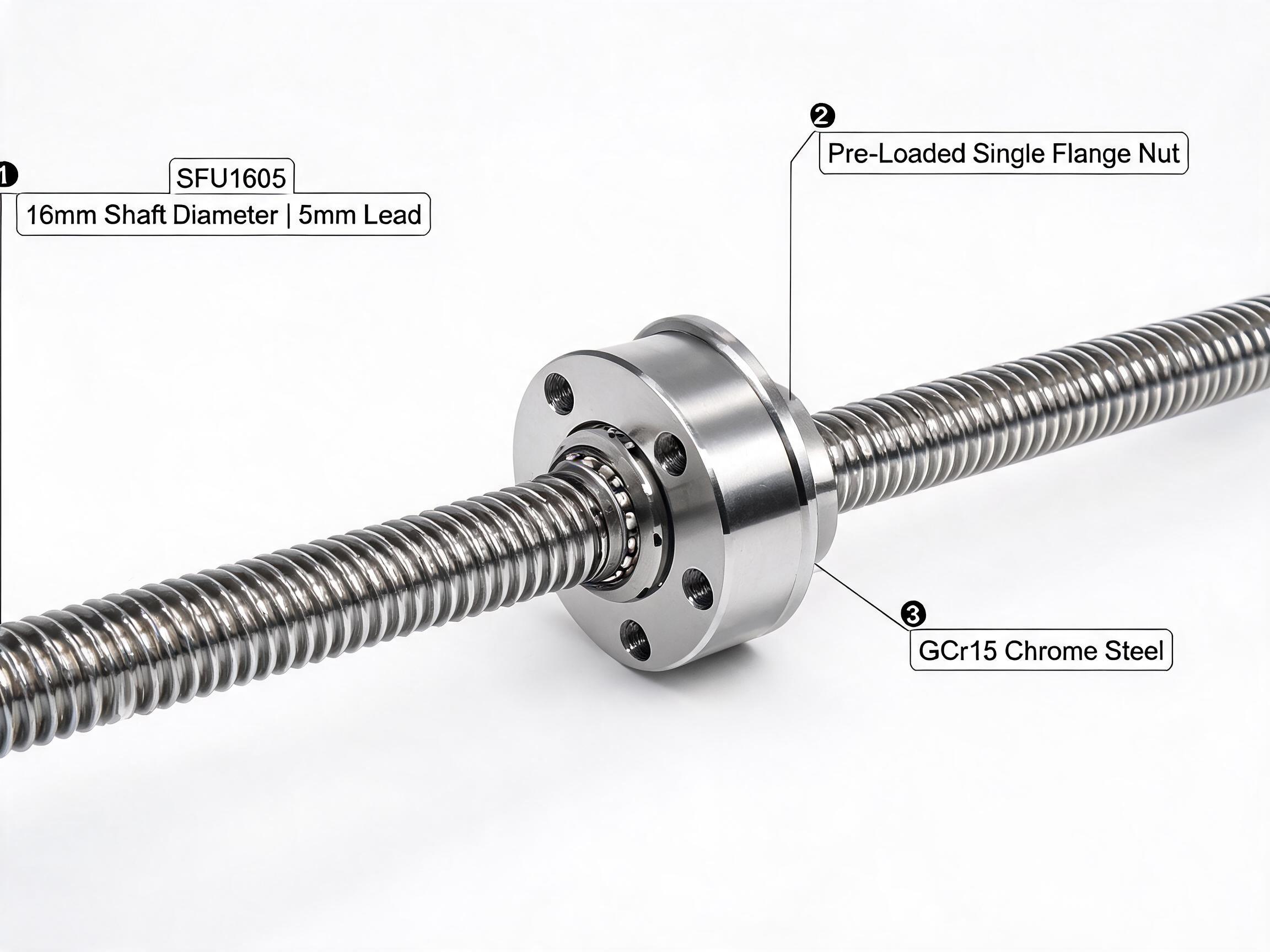
For a 16 mm shaft with 5 mm lead, the SFU1605 rolled ball screw assembly is supplied as a complete assembly with an end-machined shaft and a pre-loaded single flange nut, using a four-hole M4 flange pattern and BK12/BF12 bearing block configuration. Its shaft is GCr15 chrome steel, induction hardened to HRC 58-62, with a dynamic load of 6.8 kN for the single nut, and standard lengths from 300 mm to 1500 mm. Lubrication is by grease or oil through the nut port. In bench tests that assembly typically runs below 55 dB at 600 RPM; the figure describes the screw on a test bench, not a guarantee for noise in an installed axis.
Where the tighter figure is required, the SFE2005 ground ball screw assembly uses a 20 mm shaft and 5 mm lead, with axial play below 0.005 mm when fitted with its pre-loaded double nut, a dynamic load of 12.7 kN for the double nut, and standard lengths from 200 mm to 1200 mm. It is ground after heat treatment. The exact grade and end machining for any order are confirmed against the buyer's drawing or datasheet.
Support blocks and end machining: fixed-side versus supported-side
A ball screw is normally held by two blocks. The fixed side carries the axial load and uses a bearing pair that fixes the screw's axial position. The supported side lets the screw float axially as it expands with temperature. The journal at each end is machined to suit its block, so the two ends usually have different dimensions.
This is why journal dimensions must come from a drawing rather than a photograph. A photo can show the shape of the end, but it cannot give the diameter to the micron, the shoulder position, or the thread size. Measuring the old screw with a micrometer is the alternative when no drawing exists, and even then the result should be confirmed against a dimensioned sketch with tolerances before the order is released.
Reversal direction and backlash: what to check on the nut
Two nut-level details affect how the replacement behaves in the machine. The first is reversal direction: the direction the nut travels when the screw rotates. It is set by the handedness of the ball track and the orientation of the nut on the screw. Confirm it by rotating the old screw in the machine's normal forward direction and observing which way the nut moves. If the new assembly is installed with the nut reversed, the axis will move opposite to command.
The second is backlash. A single nut has some axial play unless it is pre-loaded. A double nut uses a spacer to create preload and reduce that play. The two figures quoted in this article belong to different products and are not a like-for-like comparison: below 0.005 mm is the axial play of the SFE2005 ground assembly fitted with its own pre-loaded double nut, while below 0.003 mm is the axial backlash of the DFU series double nut, which is offered in preload classes P0 light, P1 medium and P2 heavy over shaft diameters 16 mm to 40 mm. For a 16 mm to 40 mm shaft range, the DFU series double nut is available on those terms. A single nut is the right replacement when the original design used one and the axis can tolerate its play. A double nut is the right replacement when the machine was originally built with one, or when the application needs the lower backlash.
Pre-order checklist
- Nominal shaft diameter and lead confirmed by measurement and by counting turns over a known travel.
- Overall length recorded end to end.
- Journal diameter, journal length, and shoulder position at both ends measured with a micrometer and, where possible, checked against a drawing.
- Any end thread size and pitch, keyway width and depth, and locknut details recorded.
- Support block series identified on both the fixed side and the supported side.
- Nut flange hole pattern measured: number of holes, thread size, and hole spacing.
- Reversal direction confirmed by rotating the old screw in the machine's forward direction.
- Nut type on the old screw noted (single or double) and backlash requirement stated as a number, measured under load in both directions.
- Accuracy grade required by the machine identified, and grade confirmed with the supplier against the drawing or datasheet.
- Lubrication method (grease or oil through the nut port) confirmed as compatible with the machine's existing system.
- Drawing or dimensioned sketch prepared for the supplier to confirm end machining before the order is released.
FAQ
Can I replace a ground screw with a rolled screw to save cost?
Only if the machine's accuracy budget allows the wider lead tolerance. A C7 rolled screw has a lead accuracy of plus/minus 0.05 mm per 300 mm, while a C5 ground screw holds plus/minus 0.008 mm per 300 mm. If the axis was designed around the tighter figure, a rolled replacement may not meet the positioning requirement. The decision should be made against the machine's specification, not the price alone.
What if I cannot find a drawing of the old screw?
Measure the old screw with a micrometer and prepare a dimensioned sketch with the journal diameters, lengths, shoulder positions, thread details, and nut flange pattern. Send that sketch with the inquiry so the supplier can confirm whether a standard assembly matches or whether the end machining needs to follow your sketch.
How do I know whether I need a single nut or a double nut?
Check what was on the old screw. If it was a single nut and the axis performed acceptably, a single nut replacement is appropriate. If the machine was built with a double nut, or if the application needs lower backlash, a double nut with a preload class matched to the requirement is the right choice. The DFU series double nut, for example, is offered at below 0.003 mm axial backlash with P0, P1 or P2 preload. That figure belongs to the DFU series and should not be read as the specification of a different assembly.
Is the running noise of a replacement screw a concern?
In bench tests, the SFU1605 assembly typically runs below 55 dB at 600 RPM. Noise in the machine depends on mounting, alignment, lubrication, and the surrounding structure, so the bench figure is a reference for the screw itself rather than a guarantee for the installed axis.
To confirm a replacement ball screw for your machine, send the measured dimensions or the old screw's drawing with your inquiry. Include the quantity and the delivery window you are working to, so the supplier can confirm the end machining, accuracy grade and availability together before the order is placed.