
A practical planning guide for rebuilding worn lead screw machines with ball screws: audit the axis, choose between rolled C7 and ground C5, specify end machining to your drawing, and avoid the mistakes that sink retrofits.
Machine Rebuild Planning
A ball screw retrofit succeeds or fails on the measurements you take before you order. The screw itself is the easy part; the axis audit, nut interface and end machining drawings decide whether the assembly drops in or sits on a shelf.
This checklist is written for machine rebuilders and factory maintenance teams replacing worn trapezoidal or ACME lead screws. It covers what to measure, how to choose between rolled and ground ball screws, how to specify end machining, and the mistakes that most often turn a straightforward upgrade into a second rebuild.
Start With an Axis Audit, Not a Catalog
Before selecting a screw, record the existing axis in enough detail that a screw can be built to fit it. Every retrofit decision downstream depends on these dimensions, and a missing one usually means re-machining or a new housing.
- Available mounting space: total length between bearing blocks, and clearance around the screw, nut and flange through the full stroke.
- End journal dimensions: diameter, length, keyway size and thread at both ends of the existing screw, plus the bearing type currently fitted.
- Nut housing and flange interface: bolt pattern, bolt size, flange diameter and thickness, and the distance from nut face to the load bracket.
- Support block positions: center distance between the fixed and supported ends, and whether either block can be relocated or replaced with a BK/BF style block.
- Axis duty: load direction, stroke, whether the screw is horizontal, vertical or inclined, and the max travel speed the machine is expected to run.
Take photographs with a scale rule against each interface. A journal diameter that looks close on a tape measure can be enough off that a standard end machining will not seat correctly.
Choose the Screw Type From the Required Outcome
Two grades cover most rebuilds, and the choice turns on whether the machine needs general smooth feed or a specific positioning tolerance held repeatedly.
| Option | Grade and accuracy | Where it fits |
|---|---|---|
| SFU series (e.g. 1605, 2005) | Rolled, C7, ±0.05 mm per 300 mm | General rebuilds, feed axes on older machines where the existing control and feedback cannot hold tighter than the mechanical grade anyway |
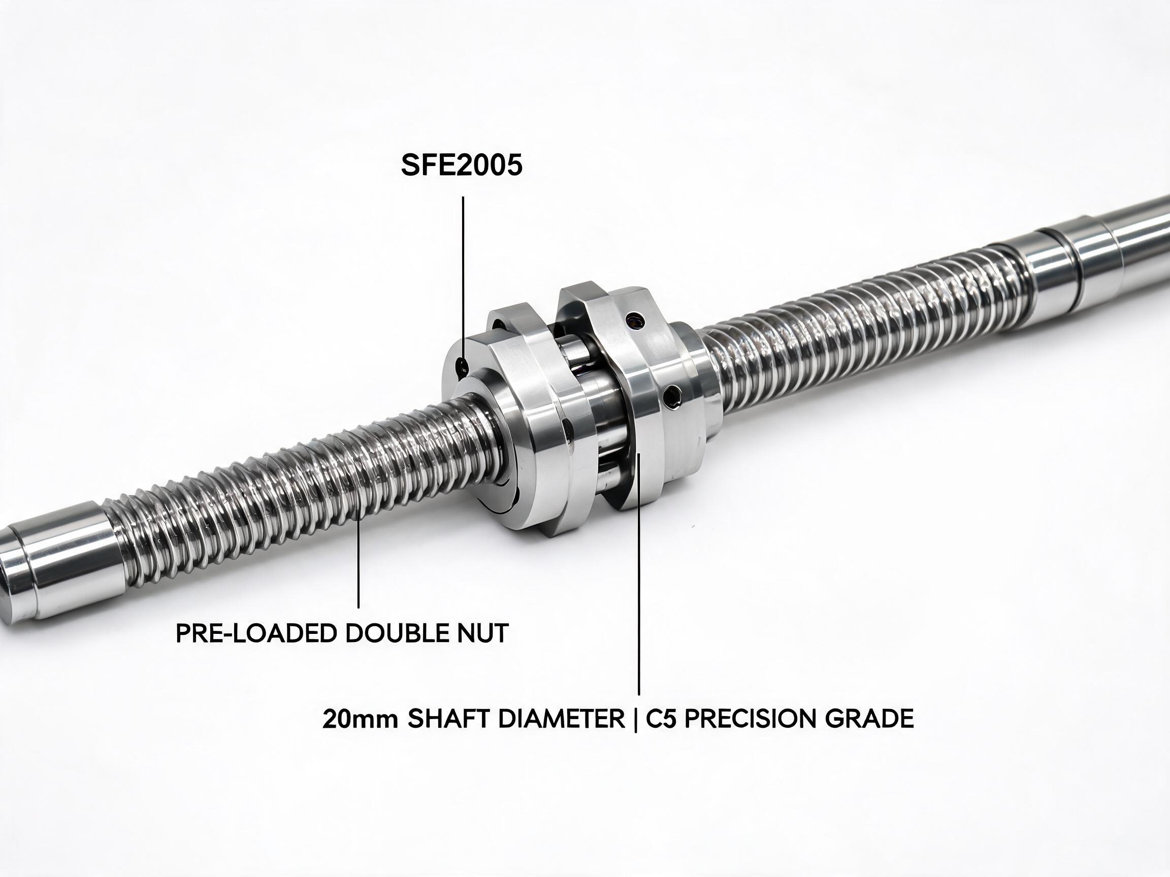
| SFE Series Ground Ball Screw Assembly | Ground, C5, ±0.008 mm per 300 mm, pre-loaded double nut | Axes where positioning tolerance matters across the stroke and the machine is expected to hold it in production |
| DFU Series Double Nut Zero-Backlash Ball Screw | Pre-loaded double nut, backlash held below 0.003 mm | Axes where reversal error is the problem being solved, not just wear |
| SFU3205 Heavy-Duty Rolled Ball Screw for CNC Machining Centers | Rolled, 32 mm diameter, 5 mm lead | Heavier rebuilds where shaft stiffness and load capacity drive the selection more than fine accuracy |
Screws in these series are made from GCr15 (52100) chrome steel with shafts induction hardened to HRC 58-62, which is the surface condition you want for a worn axis being brought back into service rather than a light-duty application.
Where the axis must hold a tight position, ground C5 is the practical floor for a rebuild without closed-loop compensation. Where the original machine was a general-purpose feed axis and the control has no scale feedback, a rolled C7 screw is usually the proportionate choice: paying for a ground screw does not improve the machine if the rest of the axis cannot resolve the difference.
Plan End Machining to the Customer Drawing
Standard assemblies ship end-machined for BK/BF bearing blocks, so a machine already using that block arrangement can often be retrofitted without new housings. That is the fast path, and it is worth checking first whether the existing support blocks match a standard BK/BF pattern before planning anything more custom.
When the existing journals do not match, end machining can be adjusted to a customer 2D drawing: journal diameter, keyway and thread are all specified from your drawing rather than from a catalog default. Prepare that drawing before requesting a screw, and include:
- Journal diameter and length with tolerance at each end.
- Keyway width, depth and position relative to a datum you define.
- Thread specification and the length of thread engaged by the locknut.
- Any shoulder or step that locates a bearing inner ring.
- The datum from which overall screw length is measured.
A drawing with a clear datum removes the most common source of fit problems. If two parties measure overall length from opposite ends, the screw arrives correct and the machine still does not assemble.
What the Retrofit Changes, and What It Does Not
Replacing a sliding lead screw with a rolling ball screw changes the axis in three predictable ways: friction drops, so the motor sees a lighter load; the nut runs with far less internal clearance, so backlash falls, with a pre-loaded double nut holding it below 0.003 mm; and motion becomes smoother at low feed because there is no stick-slip at the sliding contact.
The scale of each improvement depends on the machine. Motor load reduction, achievable speed and the resulting positioning performance all depend on the screw size, the preload, the bearing blocks, the drive tuning and the control. Confirm expected values with the datasheet and the axis calculation for your specific machine rather than assuming a general improvement figure. A retrofit does not convert an old machine into a new one; it removes the lead screw as the limiting element.
Common Retrofit Mistakes
Reusing worn bearings
The old thrust bearings and support blocks have run with the same wear as the screw. Fitting a new, pre-loaded ball screw into worn bearings puts the axial clearance back into the system, and the measured backlash will not match the nut specification. Plan new BK/BF blocks as part of the retrofit, not as an optional extra.
Mismatched nut flange pattern
A ball nut flange is not interchangeable with the old lead screw nut. If the flange bolt pattern and the nut-to-load distance are not captured in the audit, the replacement nut will not bolt to the existing bracket. Either match the pattern in the order or plan a new bracket and account for the change in the axis geometry.
Ignoring shaft whip on long spans
A long, slender screw in rotation will whip at higher speeds, and a retrofit that increases speed will expose it.
If the axis has a long unsupported span, check the critical speed for the chosen diameter against the intended maximum speed before committing. Moving to a larger diameter, such as the 32 mm SFU3205, or adding a supported end changes the answer. This calculation depends on the span and mounting arrangement; confirm it for your axis rather than relying on a rule of thumb.
Ordering before the drawing is agreed
End machining is the part of the order most likely to be wrong. Get the drawing reviewed and confirmed in writing before the screw is machined.
Retrofit Planning Checklist
- Audit the axis: space, journal dimensions, nut flange, support block positions, duty.
- Decide the required positioning accuracy and whether the control can use it.
- Select rolled C7 for general feed axes; ground C5 or a pre-loaded double nut where positioning and backlash matter.
- Confirm the bearing block arrangement and whether standard BK/BF end machining applies.
- Prepare the 2D end machining drawing with a single, stated datum.
- Check critical speed for the span and intended maximum speed.
- Budget new support bearings and any bracket changes alongside the screw.
- Confirm delivery, mounting instructions and acceptance criteria in writing.
Any figure not fixed by the screw grade — achievable speed, motor load, positioning result in service — should be confirmed against the datasheet and your axis calculation before the order is placed.