
A maintenance-focused guide to ball screws, nuts and guideways on injection molding machines: which component wears first on clamp, ejector and injection axes, how shaft diameter and lead affect sizing, and what to send with a replacement inquiry.
Injection molding machines do not wear linear motion components the way a milling center does. The clamp and ejector axes spend most of their life standing still under load, the injection axis runs short strokes at high cycle counts, and the clamp area sits in heat and purge mist. That changes which part fails first and what a correct replacement has to match.
- Why sustained holding force and short strokes move the wear item from the screw axis to the platen guideway
- How to read shaft diameter and lead as separate levers when sizing a clamp axis screw
- What rail size and bolt size mean on platens and inverted axes
- What checks to run before ordering, and what to put in the inquiry
What makes injection molding duty different
Three conditions separate this duty from general linear motion work.
Sustained static holding force. During packing and holding, the clamp stays closed and the screw or ejector holds position against a load for seconds at a time, cycle after cycle. The bearing contact is not rotating through that period; it is loaded and stationary or micro-moving. Lubricant film thickness under that condition, and the preload state of the nut, matter more than peak dynamic rating alone.
Short strokes at high cycle counts. Clamp open and close, ejector advance and return, injection screw recovery: these are short travels repeated constantly. A recirculating ball nut on a short stroke works the same few ball tracks repeatedly, and a linear bearing carriage works the same section of raceway. Wear concentrates instead of spreading over the full rail length.
Heat and purge contamination near the clamp area. Purge spray, mold release mist and barrel radiant heat reach the clamp platens and the guideways that guide them. Contamination entering a ball nut or a carriage seal is a direct route to premature wear, independent of load.
Those three conditions explain the shift from screw to guideway. On a continuously rotating, long-stroke axis the screw nut accumulates the most ball contact cycles. On a clamp axis the platen guideway carries the load and the contamination minute after minute while the screw mostly holds position, so the raceway and carriage seal take the punishment first and screw backlash only shows up as platen hesitation. On the ejector axis the cycle count is highest, so nut ball tracks and the same rail section wear together. Which item fails first is therefore set by the duty, not by the machine size.
One practical consequence: a replacement chosen only on matching the old part number can reproduce the original weakness. The better approach is to size against the axis duty, then confirm the interface dimensions.
Clamp and ejector axes versus injection axes
The load profile, not the machine size, decides which component is the wear item.
On a clamp axis, the platen moves on guideways and the force is largely transverse and static. The guideways and the carriage raceways carry the load and see the contamination. The ball screw that moves the platen often runs at low axial load but must hold position; backlash in that screw shows up as platen hesitation or position drift under hold.
On the ejector axis, strokes are short and the load is moderate, but the cycle count is highest. Ball nut contact fatigue and rail section wear both deserve attention.
On the injection axis, the screw pushes against melt pressure and holds during pack. That is where axial stiffness, preload and backlash dominate, and where a double-nut zero-backlash design earns its cost.
| Axis | Dominant load character | Likely wear item | Component direction |
|---|---|---|---|
| Clamp / platen | High static transverse load, holding position, contamination from purge area | Guideway raceway and carriage, then screw backlash under hold | Large rail with static load headroom; screw with preloaded nut |
| Ejector | Low to moderate load, very high cycle count, short stroke | Ball nut ball tracks and rail section under repeated passes | Screw with proven dynamic rating; rail matched to stroke and mounting |
| Injection | Axial push and sustained hold, position drift shows as part variation | Nut preload loss and axial play | Double-nut preloaded screw, high axial rigidity |
Where the injection axis needs zero-backlash holding, the DFU Series double nut with spacer preload is built for that condition, with axial backlash below 0.003 mm and preload classes P0 light, P1 medium and P2 heavy. Its dynamic load on the DFU2005 size is 10.2 kN, which is 1.5 times the single nut SFU2005 figure of 6.8 kN, across shaft diameters 16 to 40 mm in C7 rolled or C5 ground. See the DFU double nut zero-backlash ball screw for the preload and size range.
Sizing a replacement screw for a heavy axis
Two choices drive everything else on a screw: shaft diameter and lead. Treat them as separate decisions.
Diameter is the stiffness lever
The shaft is a beam between support bearings, and bending deflection falls sharply as diameter rises. The 32 mm shaft of the SFU3205 is stated as giving 2.5 times the bending stiffness of the 25 mm SFU2510 shaft. On a clamp or ejector axis with a long unsupported span, that difference matters before any support change is considered.
The same SFU3205 record gives a dynamic load of 22.5 kN on a single flange nut, static load 34.8 kN, GCr15 chrome steel with the shaft induction hardened to HRC 58-62, C7 per ISO 3408 with lead accuracy plus or minus 0.05 mm per 300 mm, and standard lengths from 500 to 4000 mm. Because it is supplied as a single piece up to 4000 mm, a travel whose overall length plus end machining stays within 4000 mm needs no splice joint. It is compatible with BK32 and BF32 support blocks. Full dimensions are on the SFU3205 heavy-duty rolled ball screw page.
Lead is the resolution and speed lever
A 5 mm lead gives fine position resolution per motor revolution and more axial force per unit torque, at lower linear speed for a given screw rpm. A 10 mm lead trades resolution for speed. If the axis must hold position under pressure and the drive tuning is already tight, resolution is usually the constraint, not speed.
When high accuracy is required
Where the axis needs tighter lead accuracy than C7, the SFE Series ground screw is C5 per ISO 3408 with lead accuracy plus or minus 0.008 mm per 300 mm, axial play below 0.005 mm with a pre-loaded double nut, and axial rigidity up to 280 N per micrometre under rated preload. The 20 mm shaft, 5 mm lead size carries a dynamic load of 12.7 kN.
None of this replaces the axis load case. Final diameter, lead, preload class and end machining are confirmed per drawing and datasheet.
Guideway choice on platens and heavy frames
On clamp platens and heavy moving frames, the rail is carrying static load, so static rating headroom and mounting integrity matter more than dynamic rating alone.
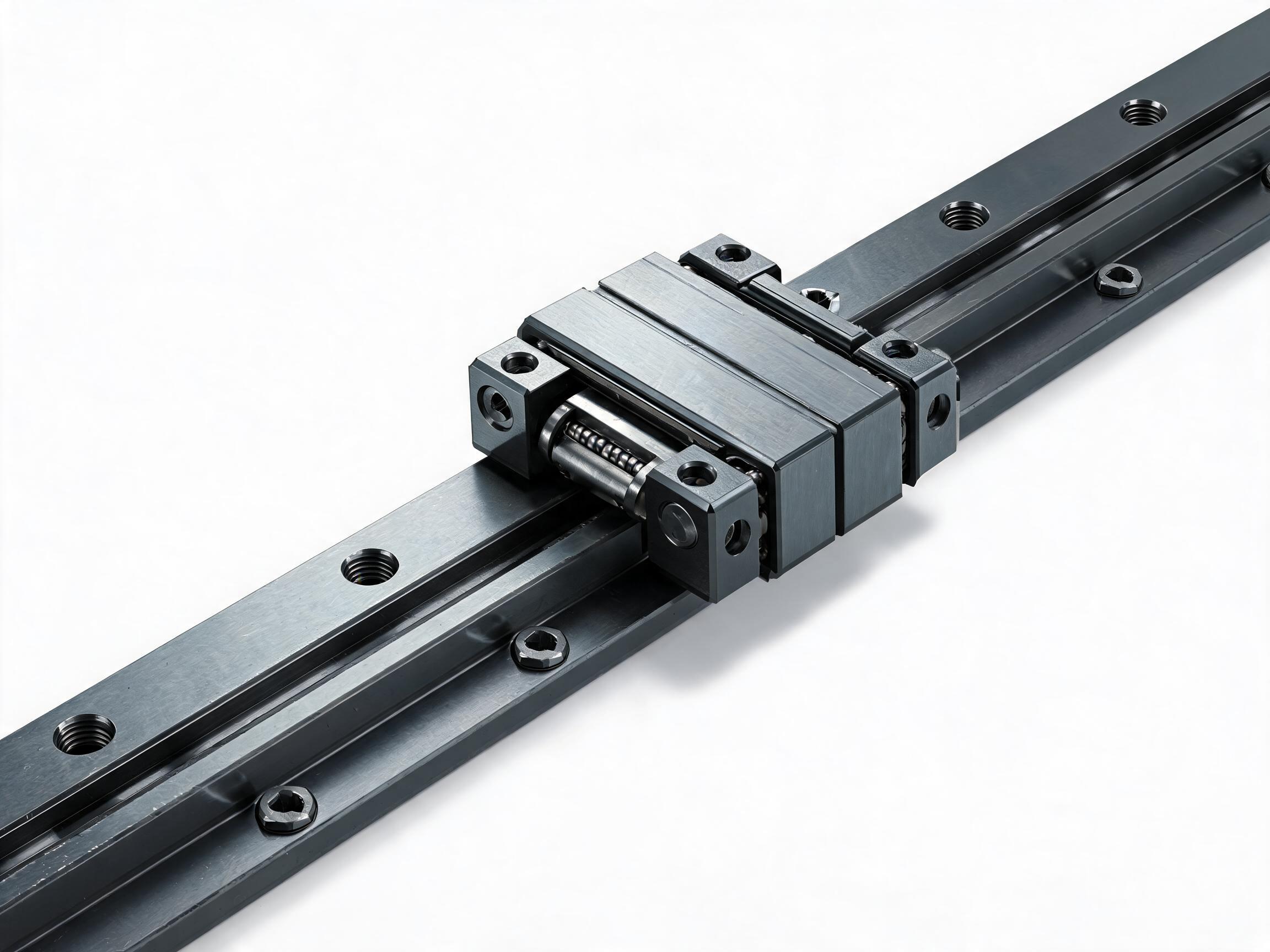
The HGR45 rail is 45 mm wide by 38 mm high in 45# high-carbon steel, surface hardness 58-62 HRC with case depth 2.0 to 2.5 mm, offered in ground H (P5) or rolled N (P7) precision grade. Paired with the HGW45CA carriage it is rated 62.8 kN dynamic and 112 kN static, with a maximum standard rail length of 4000 mm and a bolt hole pitch of 60 mm on M12 mounting bolts. Rail weight is 6.2 kg per metre. Ground P5 rails hold 0.02 mm straightness per metre with 5 micrometre raceway flatness. The record states its typical use on injection molding machine platens where static load exceeds 60 kN per axis. Details are on the HGR45 heavy-duty large linear guideway rail page.
Bolt size is a lift-off and shear concern
On a vertical or inverted axis, the mounting bolts are not just locating the rail, they are resisting lift-off and shear from the load. M12 bolts on a 60 mm pitch are a different bracket than small-rail fasteners, and the frame thread depth and material behind those bolts need to match. A rail upgrade without checking the frame's bolt engagement solves nothing.
Rail size against the load
Two numbers decide the rail size: the static load per carriage, including the platen and the mould half it carries, and the static rating of the size under consideration. Work out the static load first, then compare it with the static rating and keep the working figure below that rating; how much margin is appropriate depends on shock, thermal load and the machine builder's own design rule, so the final margin is confirmed with the supplier against the load case rather than assumed from a generic percentage. Then confirm the carriage type, preload and mounting orientation. On platens, also plan how the rail is protected from purge contamination, since the rating assumes the raceway is not being abraded.
Wear and inspection checks before ordering
Run these on the machine before the inquiry goes out. Each one turns into a fact on the drawing package.
- Axial backlash at the nut, measured with the axis loaded in both directions. Compare against the original specification; a double nut that has lost preload reads as play under hold.
- Screw shaft straightness and visible raceway marking, especially on the short stroke band where the nut actually travels.
- Lead accuracy spot check over the working stroke if the machine is producing dimensional drift that drive compensation cannot hold.
- Rail straightness along the mounting face, and raceway condition on the loaded band rather than the full length.
- Carriage play and seal condition. A damaged wiper lets contamination in and the raceway tells you how long it has been happening.
- Mounting bolt torque and thread condition, particularly on vertical or inverted axes where lift-off is a real load path.
- Lubrication state and any evidence of purge mist or mold release deposits on the rail and screw.
Record the numbers and the measurement method. Two maintenance teams can disagree about a screw only because they measured backlash at different load states.
What to put in the inquiry so the replacement matches
The most common delay in a replacement order is a missing dimension that only surfaces after the quote. Send these together:
- Drawing or sketch of the existing part, with nominal diameter, lead, nut type and flange orientation.
- Overall length and the critical lengths: thread length, journal lengths, and the distance between bearing shoulders.
- End machining detail: bearing journal diameters and tolerances, keyway or flat, thread at the drive end.
- Support block arrangement: fixed end and supported end, and whether BK32 / BF32 style blocks are retained.
- Nut preload class and backlash requirement, stated as a number rather than a description.
- Rail length, hole pattern and bolt size for guideway items, plus carriage type and mounting orientation.
- Quantity and whether it is a single replacement or a planned stock item.
Photographs of the installed part help, but they do not replace measured dimensions. If the original drawing is unavailable, measure the installed part with the axis unloaded and note that condition on the sketch.
FAQ: injection molding machine retrofits
Can I replace a single-nut screw with a double-nut design on the same axis?
Often yes, if the nut envelope and flange mounting allow it. The DFU Series covers shaft diameters 16 to 40 mm, so the question is usually whether the housing has room for the longer double nut. Confirm the envelope against the drawing before ordering.
My clamp axis screw shows no backlash but the platen still hesitates. Where else do I look?
Check the guideway and carriage first. On a clamp axis the load is largely transverse and static, so carriage play, raceway wear on the loaded band, or contamination under a damaged seal can produce hesitation that a backlash check on the screw will not show.
Is a 4000 mm single-piece screw enough for a standard machine travel?
The SFU3205 is supplied as a single piece up to 4000 mm, so a travel whose overall length plus end machining stays within that needs no splice joint. If the required length plus end machining exceeds it, the joint or an alternative configuration has to be planned, so state the overall length early.
How do I decide between C7 rolled and C5 ground?
Start from the axis requirement, not the price. C7 gives lead accuracy of plus or minus 0.05 mm per 300 mm on the SFU3205; C5 ground gives plus or minus 0.008 mm per 300 mm on the SFE Series. If the machine holds dimensions without constant compensation, C7 may be sufficient. If position drift under hold is the complaint, the tighter grade and the preloaded double nut are the levers to examine.
Send the axis load case, the measured backlash figures and the drawing dimensions together and the replacement can be confirmed against your machine rather than against a part number alone.