
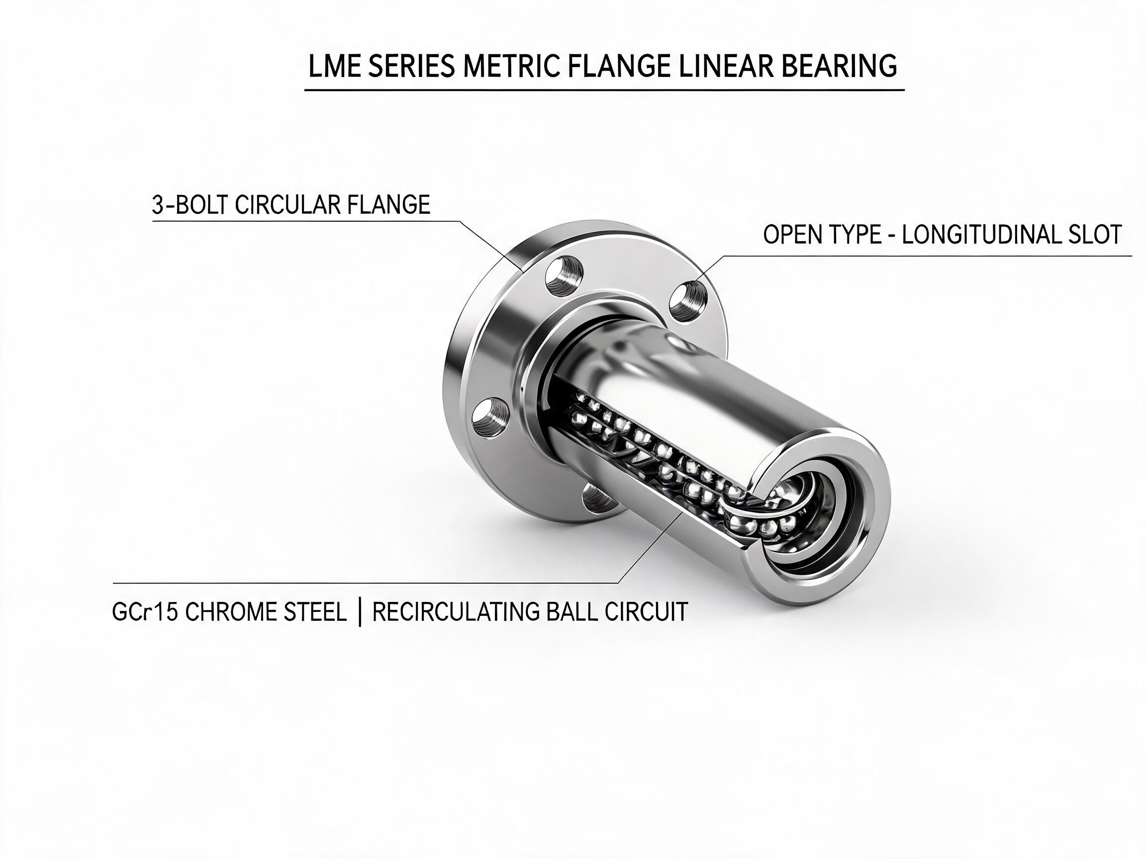
A linear guide rail drawing or linear bearing drawing determines fit before you order. This guide explains which callouts to check—envelope dimensions, mounting hole pitch, bolt size, flange bolt-circle, open-slot orientation, and straightness or grade—and what to include when sending your own machine drawing for custom hole patterns or lengths.
Procurement Guide · Linear Motion
When you match a linear rail or bearing to an existing machine, the fit is settled on paper long before the parts ship. A linear guide rail drawing or linear bearing drawing carries the callouts that determine whether the component mounts cleanly, whether the block aligns with the load, and whether the rail can be bolted to your frame without re-drilling. This article explains which dimensions to check first, how to read the callouts that control fit, and what to send when you need a custom hole pattern or length.
Key takeaways
- Envelope dimensions — overall height, width, and block length — decide whether the assembly fits the space and maintains the working height of your existing setup.
- Mounting hole pitch and bolt size are the two callouts that most often cause a rail to be unusable on an existing frame.
- Flange bolt-circle and open-slot orientation govern how a flange bearing seats in its housing; standard OP slot orientation is 90° from the flange bolt hole, with other orientations discussable for large orders.
- Straightness and grade callouts set the accuracy class you are buying — do not assume a grade from the product photo.
- For custom work, send your machine drawing with datum, hole positions, bolt size, rail length, and any splice requirement; Dongfeng Bearing can discuss custom patterns for qualified order volumes.
Start with the envelope, not the model number
Buyers often begin by searching a model code and then try to confirm it later. The drawing is a better starting point. A linear guide rail drawing fixes the rail profile: rail height (H), rail width (W), and the distance from the rail bottom to the center of the mounting holes. For a bearing block, the drawing fixes block height, block width, block length, and the position of the block mounting holes relative to the rail centerline. These envelope dimensions are cumulative. If the rail is 2 mm taller than the original, the carriage sits 2 mm higher, and every downstream alignment—belt tension, coupling height, sensor position—shifts with it.
Check the envelope against three things in your machine: the available vertical space under the carriage, the working height of the load, and the clearance around the block for the lubrication point and any end caps. On a LME series metric flange linear bearing, for example, the supplier recommends verifying outer diameter, flange diameter, bolt-circle, and overall length against the housing drawing before ordering. Those four values are the bearing's envelope, and a housing machined for a different bolt-circle will not accept the unit even if the shaft diameter matches.
Mounting hole pitch and bolt size
The mounting hole pitch is the center-to-center distance between consecutive holes along the rail. It is not an interchangeable detail. If your frame already has drilled and tapped holes, the replacement rail must repeat that pitch exactly, or you will be re-drilling the frame. The bolt size matters for the same reason: a rail drilled for M12 bolts will not seat on a frame tapped for M8 without adapters or new holes.
Compare the drawing's pitch and bolt callout against your frame drawing hole by hole, not just at the ends. A rail can share the same overall length and the same number of holes while distributing them differently. If the pattern does not match, you have two options: modify the frame, or order a rail with a custom hole pattern. For volume orders, Dongfeng Bearing can discuss custom mounting hole pitch; the SBR16 linear motion guide rail unit is supplied with mounting holes every 50 mm along the support rail as standard and 4x M5 block bolts, and custom mounting hole pitch is available for 500+ set orders when the buyer shares their drawing. The HGR45 heavy-duty guideway rail uses a 60 mm bolt hole pitch with M12 bolts; custom bolt hole patterns are discussable for 500+ piece orders against the buyer's machine frame drawing.
When the rail is longer than the frame
Long-travel machines sometimes need a rail that exceeds a single shipping length. The HGR45 rail is supplied as splice-joined sections when the required length exceeds 4000 mm. A splice introduces a joint that must be planned on the drawing, not discovered at installation. If your design calls for a joined rail, specify the joint location on the machine drawing so the splice does not fall inside the carriage's working stroke or under a concentrated load point.
Flange bolt-circle and open-slot orientation
Flange bearings add a second set of fit conditions beyond the shaft and the bearing bore. The flange bolt-circle diameter and the number of bolt holes determine whether the unit bolts to the housing face. The open-slot (OP) orientation determines where the shaft can enter and how the bearing is adjusted in service. For the LME series, the standard OP slot orientation is 90° from the flange bolt hole. Other orientations can be discussed for large orders, but they must be stated on the request because the default is not universal.
Read the flange callouts against the housing drawing in this order: bolt-circle diameter, bolt hole count, flange outside diameter, and slot orientation. A housing with four bolt holes will not accept a three-bolt circular flange, and a slot rotated from the expected position can block shaft insertion or place the adjustment access on the wrong side of the housing. These are drawing checks, not installation fixes.
| Drawing callout | What it controls | What to compare it against |
|---|---|---|
| Rail height and width (envelope) | Working height and space around the carriage | Machine frame clearance and load height |
| Mounting hole pitch | Whether the rail bolts to existing tapped holes | Frame hole pattern, hole by hole |
| Bolt size (e.g., M5, M12) | Fastener fit and clamp load capacity | Frame tap size and bolt length available |
| Flange bolt-circle diameter | Whether the bearing seats on the housing face | Housing bolt positions and face diameter |
| OP slot orientation | Shaft entry and adjustment access | Housing access direction and assembly sequence |
| Straightness / grade callout | Accuracy class of the rail | Machine positioning requirement |
| Splice joint (if any) | Continuity of long rails | Carriage stroke and load path |
Straightness and grade callouts
Straightness and grade callouts on a linear guide rail drawing define the accuracy class of the rail as supplied. They are not interchangeable with the nominal dimensions. Two rails can share the same envelope and hole pattern while carrying different grade callouts. The drawing you approve should state the grade you are ordering, and your purchase order should reference that drawing revision. If your machine's positioning requirement is not stated on the drawing, the grade cannot be verified from the part number alone—ask for the grade callout in writing and compare it to the machine's accuracy requirement before the order is released.
The same discipline applies to a linear bearing drawing: bore size, outer diameter, width, and any preload or clearance notation belong on the controlled drawing. A drawing that shows only the bore and the model code is incomplete for a replacement decision.
What to send when you request custom work
Custom hole patterns and lengths are workable when the request carries the information the supplier needs to reproduce your frame. A complete request package contains:
- Your machine frame drawing with a clear datum — an edge, a bore, or a reference hole — from which all hole positions are dimensioned.
- Hole positions as coordinate values from the datum, not as a chain of dimensions that can accumulate error.
- Bolt size and thread for each hole, including any mixed sizes.
- Rail length and end conditions — whether the rail is cut square, chamfered, or joined, and where the joint may fall.
- The mating bearing or block drawing, if you are matching a pair, so the rail and block are checked as a set.
- The order volume, since custom patterns are discussed at defined volumes such as 500+ set orders for the SBR16 and 500+ piece orders for the HGR45.
A drawing with a clear datum and coordinate hole positions is easier to reproduce than a drawing with stacked dimensions. If your frame drawing lacks a datum, add one before sending. This is a drafting step, not a supplier task.
Where Dongfeng Bearing fits the decision
Dongfeng Bearing supplies linear rails and bearings against the drawing callouts discussed here. The practical next step is to place the supplier's drawing and your machine drawing side by side and check the table above in order: envelope, pitch, bolt size, bolt-circle, slot orientation, grade. Where the standard does not match, state the required hole pattern, length, or slot orientation and the order volume in the request, and the custom option can be evaluated against the machine drawing you provide. For a first check, review the LME flange bearing dimensions against your housing drawing, or the HGR45 rail specification against your frame hole pattern, before the purchase order is drafted.