Linear Slide Rail Guide Systems for Industrial Automation
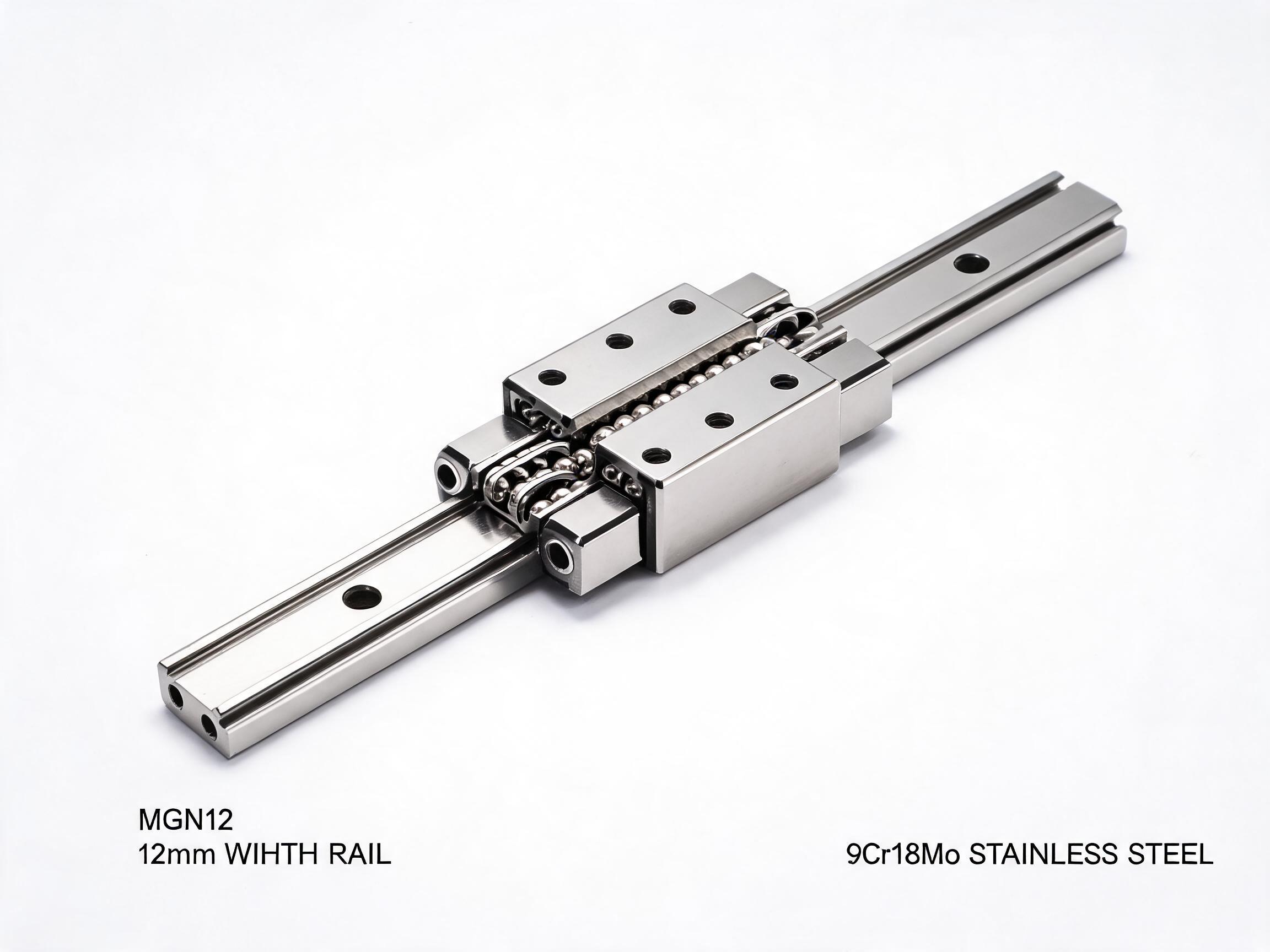
A linear slide rail guide is a complete motion system combining a precision rail, carriage blocks, and mounting infrastructure to enable guided linear movement in automated machinery, production lines, and material handling systems. Unlike standalone rails selected for a single axis, linear slide rail guide systems address the integration challenges of multi-axis configurations, drive coupling, motor mounting, and end-of-travel positioning in automated equipment. Dongfeng Bearing supplies linear slide rail guide systems built around HGR rails (15-45 mm), SBR and TBR integrated slide units, and SKF20 aluminum profile slide modules, each configured for specific automation scenarios from packaging lines to multi-axis gantry systems.
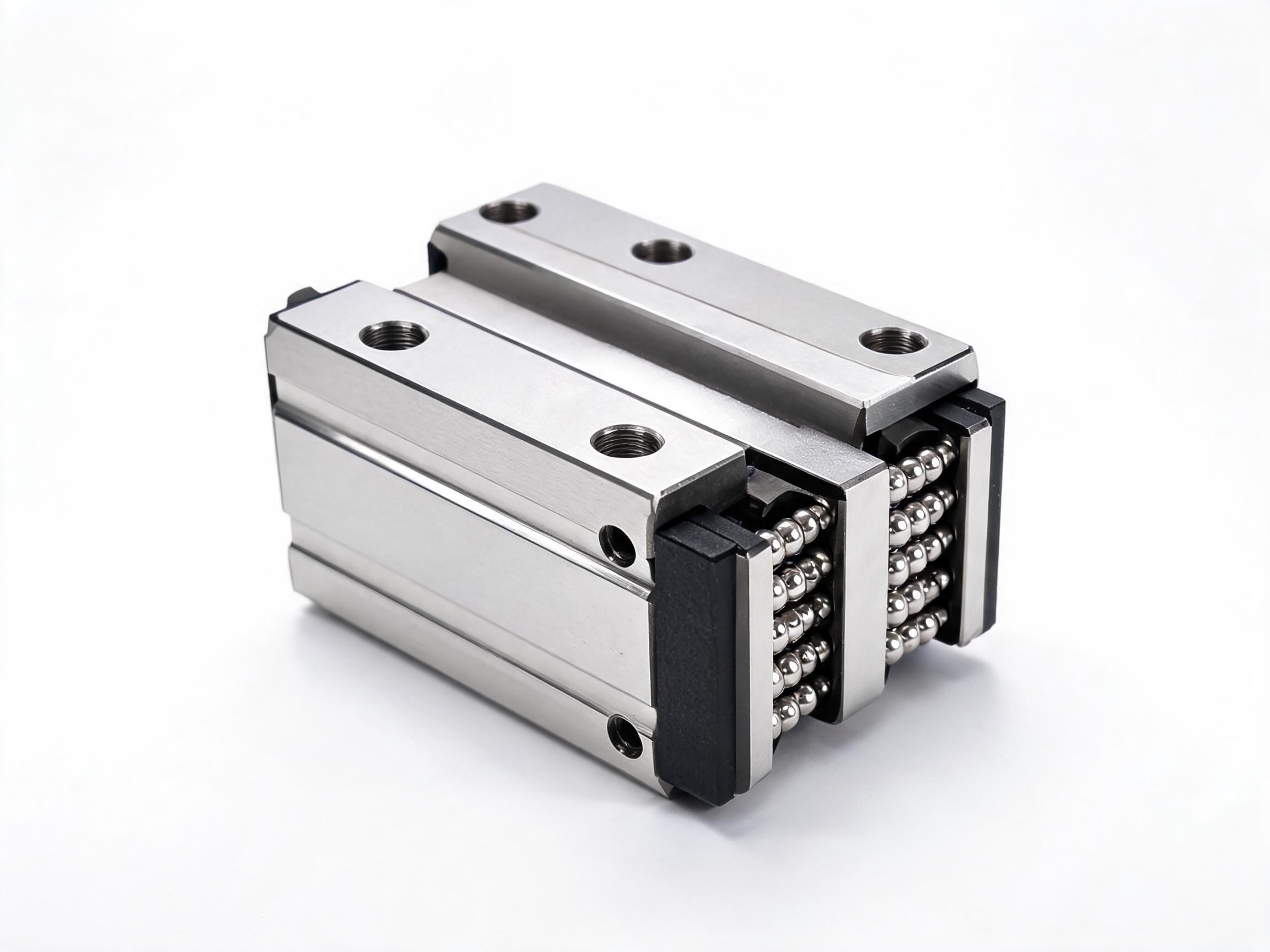
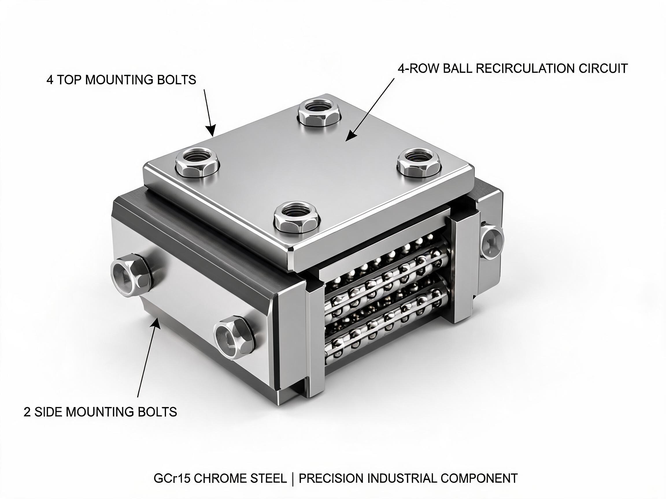
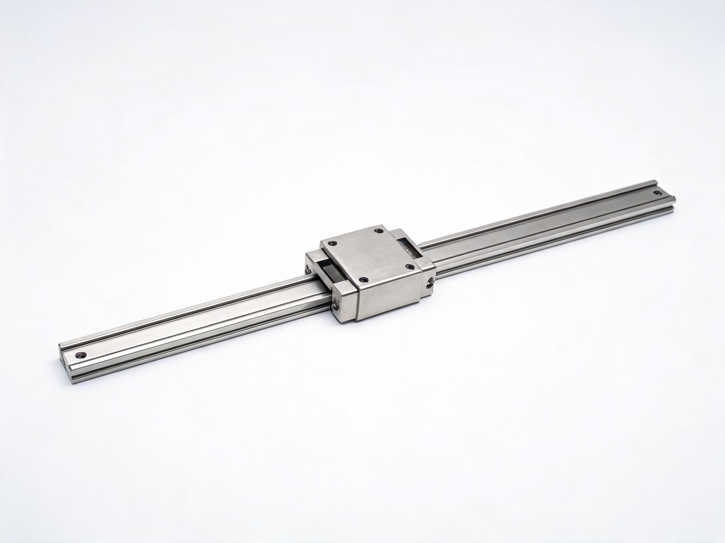
The distinction between a guideway rail and a slide rail guide system lies in the level of integration. A guideway rail provides the rolling contact surface; a slide rail guide system includes the rail, carriage, support blocks, end mounts, and often the drive mechanism interface. SBR and TBR series integrate the rail and bearing block into a single unit with pre-drilled mounting holes, simplifying installation for automation builders. The SKF20 aluminum profile slide module combines a linear guide with an aluminum extrusion frame, providing a lightweight structural platform for pick-and-place and dispensing applications.
| System Type | Series | Rail Width | Load Range | Best For |
|---|---|---|---|---|
| Integrated slide unit | SBR16/SBR20 | 16/20 mm | 3-8 kN | Packaging, material handling |
| Dual-shaft guide | TBR16 | 16 mm | 3-6 kN | Synchronized dual-axis motion |
| Profile slide module | SKF20 | 20 mm | 5-10 kN | Pick-and-place, dispensing |
| Precision cross slide | XY200 | 20 mm | 5-10 kN | XY positioning tables |
| Heavy-duty guide | HGR20-45 | 20-45 mm | 14.7-168 kN | Machine tools, gantry |
SBR and TBR Integrated Slide Guide Units
The SBR16 and SBR20 slide units combine a supported round shaft rail with linear ball bearing blocks in a pre-assembled package. The shaft is supported along its full length by an aluminum support rail, eliminating shaft deflection under load. SBR16 supports dynamic loads up to 3 kN per bearing block; SBR20 up to 8 kN with dual blocks. The TBR16 uses two parallel shafts with synchronized bearing blocks for applications requiring resistance to rotational moments without a second rail. These integrated units simplify automation design by eliminating the need for custom rail mounting and carriage selection.
Multi-Axis Gantry Systems with Linear Slide Guides
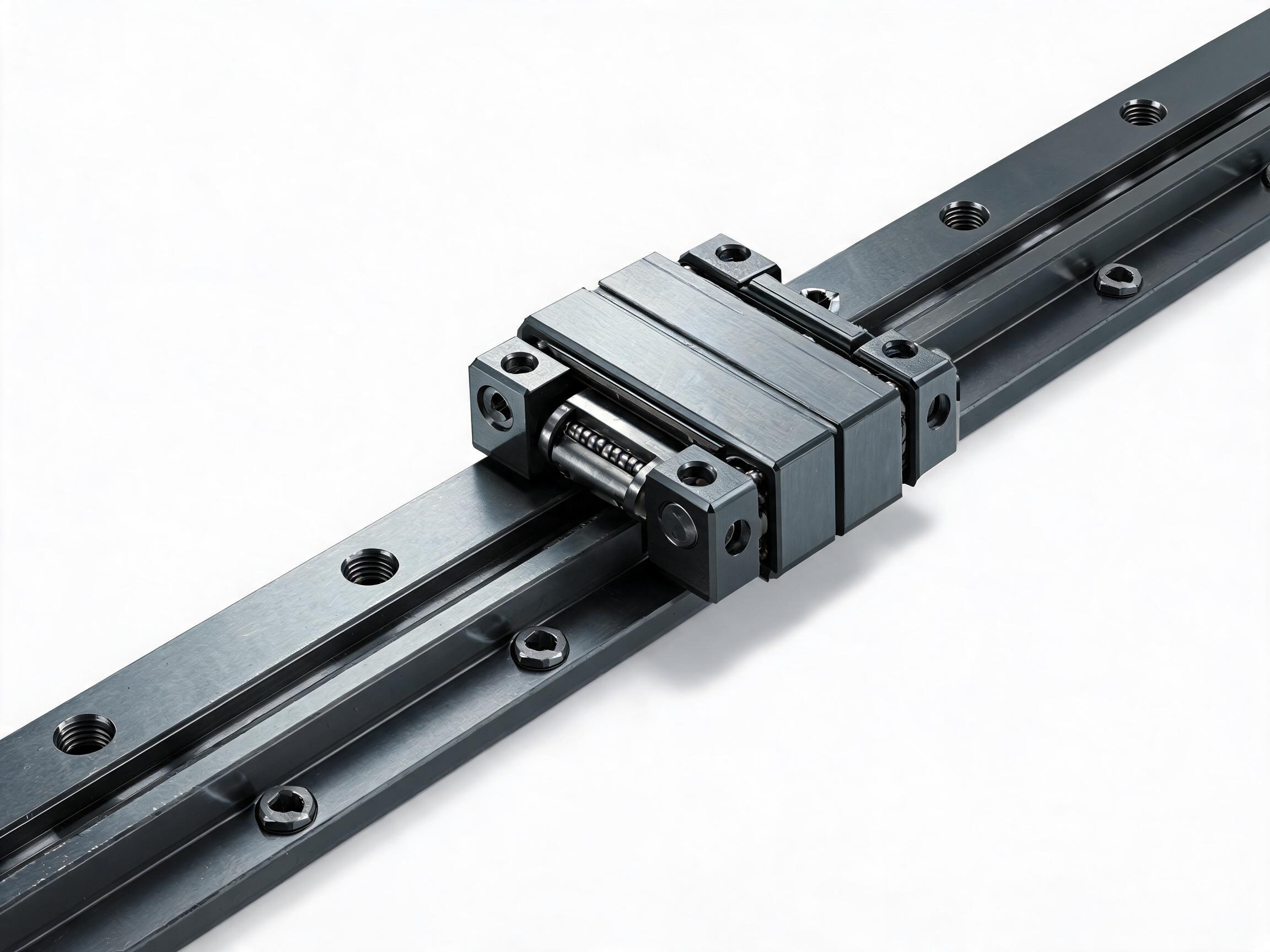
In a portal gantry system, two parallel HGR rails form the X-axis, a bridge rail forms the Y-axis, and a vertical rail forms the Z-axis. The bridge rail is supported at both ends by carriages on the X-axis rails, requiring HGW wide-body carriages for moment load capacity. For a 1000 mm bridge span with 20 kg payload, HGR25 rails with HGW25 carriages provide sufficient rigidity. For larger gantries with 2000 mm span and 50 kg payload, HGR30 or HGR35 rails are required. Drive synchronization between the two X-axis rails is critical; use a single drive shaft with torque limiters or dual servo motors with electronic synchronization.
Drive Mechanism Integration for Slide Guide Systems
Linear slide rail guides are typically paired with ball screws, belt drives, or linear motors for actuation. Ball screw drives provide positioning accuracy to 0.01 mm and high thrust force, ideal for CNC and precision automation. Belt drives offer speeds up to 5 m/s with lower precision (0.1 mm), suitable for packaging and material handling. The drive is mounted parallel to the guide rail with the carriage block connected to the drive nut or belt clamp. For HGR systems, the carriage block features tapped holes for drive component mounting. For SBR and TBR units, the bearing block includes mounting threads for drive nuts.
| Drive Type | Max Speed | Positioning Accuracy | Thrust Force | Best For |
|---|---|---|---|---|
| Ball screw (C7) | 1 m/s | 0.01 mm | High | CNC, precision automation |
| Ball screw (C5) | 1 m/s | 0.005 mm | High | Metrology, semiconductor |
| Belt drive | 5 m/s | 0.1 mm | Medium | Packaging, handling |
| Linear motor | 3 m/s | 0.001 mm | Low-Medium | High-speed precision |
Selecting Slide Guide Systems by Application Scenario
For packaging machines with moderate loads and speeds, SBR16 or SBR20 integrated units with belt drives provide cost-effective guided motion. For pick-and-place robots in electronics assembly, SKF20 aluminum profile slide modules with ball screw drives offer lightweight precision. For CNC routers and machining centers, HGR rails with HGH or HGW carriages and precision ball screws deliver the required accuracy and rigidity. For XY positioning tables in inspection equipment, the XY200 cross slide table integrates two perpendicular axes with dual ball screw drives for sub-millimeter positioning.
Load Distribution in Multi-Carriage Slide Systems
In systems with multiple carriages on a single rail, load distribution depends on carriage spacing and load application point. For evenly distributed loads with carriages spaced at one-third of the rail length, each carriage carries approximately one-third of the total load. For offset loads, the carriage nearest the load point carries a disproportionate share. Use the beam formula to calculate individual carriage loads: for two carriages spaced L apart with load P at distance a from the first carriage, the first carriage carries P times (L minus a) divided by L and the second carries P times a divided by L. Ensure no carriage exceeds its dynamic load rating.
Installation and Alignment of Slide Guide Systems
For integrated SBR and TBR units, bolt the support rail directly to the machine frame at the pre-drilled mounting points. Verify shaft straightness by measuring carriage motion resistance across the full travel; consistent resistance indicates proper alignment. For HGR-based systems, follow standard rail installation procedures with mounting surface flatness of 0.02 mm per 300 mm. For multi-axis systems, align the primary axis first, then square the secondary axis within 0.02 mm per 300 mm using a precision square or laser alignment tool. After installation, run the system through full travel cycles to verify smooth motion and absence of binding.
Maintenance and Service Life Planning
For automation systems operating 4000-6000 hours per year, schedule relubrication every 500 hours for HGR systems and every 300 hours for SBR and TBR units with open bearing blocks. Inspect carriage seals quarterly in environments with dust or debris. Monitor carriage running resistance; a 20 percent increase over baseline indicates ball circuit wear or contamination. Plan carriage replacement at 70-80 percent of calculated L10 life to prevent unplanned downtime. For multi-axis systems, synchronize maintenance intervals across axes to minimize machine downtime.
Quality Assurance for Slide Guide Systems
Each slide guide system shipment includes CMM inspection of rail parallelism, carriage height consistency, and mounting hole positions. For integrated SBR and TBR units, shaft straightness is verified within 0.05 mm per 1000 mm. Material certificates confirm GCr15 steel composition and 58-62 HRC hardness. CE conformity, SGS material test reports, RoHS, and REACH compliance are standard. 24-month warranty covers manufacturing defects in rails, carriages, and integrated components.
Frequently Asked Questions
What is the difference between a linear slide rail guide and a standalone guideway rail?
A standalone guideway rail provides only the rolling contact surface. A linear slide rail guide system includes the rail, carriage, support blocks, and often the drive interface, providing a more complete motion solution for automation equipment.
What are SBR and TBR slide units?
SBR units combine a supported round shaft with linear ball bearing blocks in a pre-assembled package. TBR16 uses two parallel shafts with synchronized blocks for moment load resistance without a second rail. Both simplify automation design.
How do I select a slide guide system for a packaging machine?
For moderate loads (3-8 kN) and speeds, SBR16 or SBR20 integrated units with belt drives provide cost-effective motion. For higher precision, pair HGR rails with ball screw drives. Consider environmental factors like washdown requirements.
What drive mechanisms work with linear slide guides?
Ball screws for precision (0.01 mm accuracy, high thrust), belt drives for speed (up to 5 m/s, 0.1 mm accuracy), and linear motors for high-speed precision. The carriage block features mounting holes for drive component attachment.
How do I configure a multi-axis gantry system?
Use two parallel HGR rails for the X-axis, a bridge rail for Y, and a vertical rail for Z. HGW wide-body carriages on the X-axis handle bridge moment loads. Ensure drive synchronization between X-axis rails using a single shaft or electronic synchronization.
What is the XY200 cross slide table?
The XY200 is an integrated two-axis positioning table with perpendicular HGR20 rails and dual ball screw drives, providing sub-millimeter XY positioning for inspection equipment, assembly stations, and metrology applications.
How often should slide guide systems be lubricated?
HGR systems: every 500 hours. SBR and TBR open bearing units: every 300 hours. Inspect seals quarterly in contaminated environments. Monitor running resistance; a 20 percent increase indicates wear or contamination.
What is the maximum speed for slide guide systems?
HGR-based systems support up to 120 m/min with ball screw drives limited to about 1 m/s. Belt drive systems reach 5 m/s. Actual speed depends on drive mechanism, preload, lubrication, and load conditions.
Are integrated slide units interchangeable with HGR systems?
SBR and TBR units use round shaft guides, different from HGR profile rails. They are not interchangeable but serve different application needs. HGR provides higher precision and load capacity; SBR offers simpler installation.
What certifications are provided with slide guide systems?
CE conformity, SGS material test reports, RoHS, REACH compliance, CMM inspection data, shaft straightness reports for SBR units, and material certificates. 24-month warranty from shipment date.